Toyota Corolla Cross: Lost Communication with Hybrid/EV Powertrain Control Module (ch5) (System 2) Missing Message (U11B300,U11B387)
DESCRIPTION
The motor generator control ECU, which is built into the inverter with converter assembly, controls the motor (MG2) based on commands from the hybrid vehicle control ECU.
The motor generator control ECU (MG ECU) monitors communication data and detects malfunctions.
|
DTC No. | Detection Item |
DTC Detection Condition |
Trouble Area | MIL |
Warning Indicate | Note |
|---|---|---|---|---|---|---|
|
U11B300 | Lost Communication with Hybrid/EV Powertrain Control Module (ch5) (System 2) Missing Message |
Error in reception from hybrid vehicle control ECU via serial communication (out of communication standard) (1 trip detection logic) |
| Comes on |
Master Warning: Comes on |
SAE Code: U11B3 |
|
U11B387 | Lost Communication with Hybrid/EV Powertrain Control Module (ch5) Missing Message |
Error in reception from hybrid vehicle control ECU via serial communication (out of communication standard) (1 trip detection logic) |
| Comes on |
Master Warning: Comes on |
SAE Code: U11B3 |
MONITOR DESCRIPTION
The motor generator control ECU (MG ECU) monitors communication data and detects malfunctions, it will illuminate the MIL and store a DTC.
MONITOR STRATEGY
|
Related DTCs | U11B3 (INF U11B300/U11B387): Lost Communication With Hybrid Control Module |
|
Required sensors / components | Motor inverter |
|
Frequency of operation | Continuous |
|
Duration | TMC's intellectual property |
|
MIL operation | Immediately |
|
Sequence of operation | None |
TYPICAL ENABLING CONDITIONS
|
The monitor will run whenever the following DTCs are not stored |
TMC's intellectual property |
| Other conditions belong to TMC's intellectual property |
- |
TYPICAL MALFUNCTION THRESHOLDS
|
TMC's intellectual property |
- |
COMPONENT OPERATING RANGE
|
Motor generator control ECU | DTC U11B3 (INF U11B300/ U11B387) is not detected |
CONFIRMATION DRIVING PATTERN
HINT:
- After repair has been completed, clear the DTC and then check that the vehicle has returned to normal by performing the following All Readiness check procedure.
Click here
.gif)
- When clearing the permanent DTCs, refer to the "CLEAR PERMANENT DTC" procedure.
Click here
- Clear the DTCs (even if no DTCs are stored, perform the clear DTC procedure).
- Turn the ignition switch off and wait for 2 minutes or more.
- Turn the ignition switch to ON and wait for 2 minutes or more. [*1]
HINT:
[*1]: Normal judgment procedure.
The normal judgment procedure is used to complete DTC judgment and also used when clearing permanent DTCs.
- Enter the following menus: Powertrain / Motor Generator / Utility / All Readiness.
- Check the DTC judgment result.
HINT:
- If the judgment result shows NORMAL, the system is normal.
- If the judgment result shows ABNORMAL, the system has a malfunction.
- If the judgment result shows INCOMPLETE, perform the normal judgment procedure again.
WIRING DIAGRAM
Refer to the wiring diagram for the Inverter Low-voltage Circuit.
Click here
CAUTION / NOTICE / HINT
CAUTION:
Refer to the precautions before inspecting high voltage circuit.
Click here
NOTICE:
- After the ignition switch is turned off, there may be a waiting time before disconnecting the negative (-) auxiliary battery terminal.
Click here
- When disconnecting and reconnecting the auxiliary battery.
HINT:
When disconnecting and reconnecting the auxiliary battery, there is an automatic learning function that completes learning when the respective system is used.
Click here
PROCEDURE
|
1. | CLEAR DTC |
(a) Clear the DTCs.
Powertrain > Motor Generator > Clear DTCs(b) Turn the ignition switch off.
|
.gif)
|
2. | CHECK DIAGNOSIS RELATED INFORMATION AND DTC OUTPUT (MOTOR GENERATOR) |
(a) Turn the ignition switch to ON and wait for 2 minutes or more.
(b) Check for DTCs.
Powertrain > Motor Generator > Utility|
Tester Display |
|---|
|
Diagnosis Related Information |
|
Result | Proceed to |
|---|---|
|
U11B300 or U11B387 is listed in Diagnosis Related Information or U11B300 or U11B387 is output. |
A |
| U11B300 or U11B387 are not listed in Diagnosis Information and U11B300 and U11B387 are not output. |
B |
(c) Turn the ignition switch off.
| B | .gif) | CHECK FOR INTERMITTENT PROBLEMS |
|
|
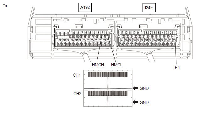
3. | CHECK HYBRID VEHICLE CONTROL ECU (CHECK WAVEFORM) |
(a) Connect an oscilloscope between the hybrid vehicle control ECU terminals specified in the following table.
(b) Turn the ignition switch to ON.
(c) Measure the waveform.
|
*a | Component with harness connected (Hybrid Vehicle Control ECU) |
- | - |
|
Item | Contents |
|---|---|
|
Tester Connection |
CH1: A192-2 (HMCH) - I249-1 (E1) CH2: A192-1 (HMCL) - I249-1 (E1) |
|
Equipment Setting |
1 V/DIV., 200 μs./DIV. |
|
Condition | Ignition switch ON |
| Result |
Proceed to |
|---|---|
| The waveform appears as shown in the illustration. |
A |
| The waveform differs from the one shown in the illustration. |
B |
HINT:
- Perform this inspection with the connector connected.
- If pulses are generated, the shape of the waveform can be assumed to be normal.
- The shape of the waveform may vary according to communication conditions.
(d) Turn the ignition switch off.
| A | | REPLACE INVERTER WITH CONVERTER ASSEMBLY |
|
|
4. | CHECK CONNECTOR CONNECTION CONDITION (HYBRID VEHICLE CONTROL ECU CONNECTOR) |
Click here
| NG | | CONNECT SECURELY |
|
|
5. | CHECK CONNECTOR CONNECTION CONDITION (INVERTER WITH CONVERTER ASSEMBLY CONNECTOR) |
Click here
|
Result | Proceed to |
|---|---|
|
OK | A |
|
NG (The connector is not connected securely.) |
B |
| NG (The terminals are not making secure contact or are deformed, or water or foreign matter exists in the connector.) |
C |
| B | | CONNECT SECURELY |
| C | | REPAIR OR REPLACE HARNESS OR CONNECTOR |
|
|
6. | CHECK HARNESS AND CONNECTOR (HYBRID VEHICLE CONTROL ECU - INVERTER WITH CONVERTER ASSEMBLY) |
CAUTION:
Be sure to wear insulated gloves.
(a) Check that the service plug grip is not installed.
NOTICE:
After removing the service plug grip, do not turn the ignition switch to ON (READY), unless instructed by the repair manual because this may cause a malfunction.
(b) Disconnect the inverter with converter assembly connector.
(c) Disconnect the hybrid vehicle control ECU connector.
(d) Measure the resistance according to the value(s) in the table below.
Standard Resistance (Check for Open):
|
Tester Connection | Condition |
Specified Condition |
|---|---|---|
|
A187-29 (HMCH) - A192-2 (HMCH) |
Ignition switch off |
Below 1 Ω |
|
A187-30 (HMCL) - A192-1 (HMCL) |
Ignition switch off |
Below 1 Ω |
Standard Resistance (Check for Short):
|
Tester Connection | Condition |
Specified Condition |
|---|---|---|
|
A187-29 (HMCH) or A192-2 (HMCH) - Body ground and other terminals |
Ignition switch off |
10 kΩ or higher |
|
A187-30 (HMCL) or A192-1 (HMCL) - Body ground and other terminals |
Ignition switch off |
10 kΩ or higher |
(e) Connect the cable to the negative (-) auxiliary battery terminal.
(f) Turn the ignition switch to ON.
(g) Measure the voltage according to the value(s) in the table below.
Standard Voltage:
|
Tester Connection | Condition |
Specified Condition |
|---|---|---|
|
A187-29 (HMCH) or A192-2 (HMCH) - Body ground and other terminals |
Ignition switch ON |
Below 1 V |
|
A187-30 (HMCL) or A192-1 (HMCL) - Body ground and other terminals |
Ignition switch ON |
Below 1 V |
NOTICE:
Turning the ignition switch to ON with the hybrid vehicle control ECU and inverter with converter assembly connectors disconnected causes other DTCs to be stored. Clear the DTCs after performing this inspection.
HINT:
As there might be an intermittent malfunction, inspect the following items even if the measured resistance is as specified.
Check that each connector between the inverter with converter assembly and hybrid vehicle control ECU is not loose or disconnected.
(h) Turn the ignition switch off.
(i) Reconnect the hybrid vehicle control ECU connector.
(j) Reconnect the inverter with converter assembly connector.
| NG | | REPAIR OR REPLACE HARNESS OR CONNECTOR |
|
|
7. | CHECK INVERTER WITH CONVERTER ASSEMBLY |
(a) Disconnect the hybrid vehicle control ECU connector.
(b) Measure the resistance according to the value(s) in the table below.
Standard Resistance:
|
Tester Connection | Condition |
Specified Condition |
|---|---|---|
|
A192-2 (HMCH) - A192-1 (HMCL) |
Ignition switch off |
80 to 170 Ω |
(c) Reconnect the hybrid vehicle control ECU connector.
| OK | | REPLACE HYBRID VEHICLE CONTROL ECU |
| NG | | REPLACE INVERTER WITH CONVERTER ASSEMBLY |
READ NEXT:
 Relay
Relay
On-vehicle InspectionON-VEHICLE INSPECTION PROCEDURE
1. INSPECT IGCT RELAY (IGCT)
(a) Measure the resistance according to the value(s) in the table below.
Standard Resistance:
T
Removal
REMOVAL CAUTION / NOTICE / HINT COMPONENTS (REMOVAL)
Procedure Part Name Code
1 CHECK FOR DTC
- -
-
2 NEGATIVE AUXILIA
SEE MORE:
 Freeze Frame Data
FREEZE FRAME DATA
FREEZE FRAME DATA
(a) When a DTC is stored, the 4WD ECU assembly stores the current vehicle state
as Freeze Frame Data.
HINT:
Freeze Frame Data at the time a DTC is stored:
When the 4WD ECU assembly stores data at the time a DTC is stored, no updates
will be performed
Hybrid/EV Battery ECU Multiple Reset (P1AFF00)
DESCRIPTION The battery ECU assembly monitors its internal operation and will store these DTCs when it detects an internal malfunction.
DTC No. Detection Item
DTC Detection Condition
Trouble Area MIL
Warning Indicate Note
P1AFF00 Hybrid/EV Battery ECU Multip
