Toyota Corolla Cross: Lost Communication with Airbag System Control Module Circuit Short to Auxiliary Battery or Open (P310715)
DESCRIPTION
Refer to the description for DTC P310711.
Click here .gif)
|
DTC No. | Detection Item |
DTC Detection Condition |
Trouble Area | MIL |
Warning Indicate | Note |
|---|---|---|---|---|---|---|
|
P310715 | Lost Communication with Airbag System Control Module Circuit Short to Auxiliary Battery or Open |
Open or short to +B in the communication circuit Communication from the airbag ECU assembly stopped and Circuit High has been detected for a certain period. (1 trip detection logic) |
| Does not come on |
Master Warning: Comes on |
SAE Code: P3107 |
CONFIRMATION DRIVING PATTERN
HINT:
After repairs have been completed, clear the DTCs and then check that the vehicle has returned to normal by performing the following All Readiness check procedure.
Click here
- Connect the GTS to the DLC3.
- Turn the ignition switch to ON and turn the GTS on.
- Clear the DTCs (even if no DTCs are stored, perform the clear DTC procedure).
- Turn the ignition switch off and wait for 2 minutes or more.
- Turn the ignition switch to ON and turn the GTS on.
- With ignition switch to ON and wait for 15 seconds or more.
- Enter the following menus: Powertrain / Hybrid Control / Utility / All Readiness.
- Check the DTC judgment result.
HINT:
- If the judgment result shows NORMAL, the system is normal.
- If the judgment result shows ABNORMAL, the system has a malfunction.
- If the judgment result shows INCOMPLETE or N/A, perform driving pattern again.
WIRING DIAGRAM
Refer to the wiring diagram for DTC P310711.
Click here
PROCEDURE
|
1. | CHECK DTC OUTPUT (SRS AIRBAG) |
(a) Check for DTCs.
Body Electrical > SRS Airbag > Trouble Codes| Result |
Proceed to |
|---|---|
| DTCs are not output |
A |
| DTCs are output |
B |
| B | .gif) | GO TO DTC CHART (AIRBAG SYSTEM) |
|
.gif)
|
2. | CHECK AIRBAG ECU ASSEMBLY (CHECK WAVEFORM) |
Click here
| Result |
Proceed to |
|---|---|
| The waveform appears as shown in the illustration |
A |
| The waveform differs from the one shown in the illustration |
B |
| B | | GO TO STEP 6 |
|
|
3. | CLEAR DTC |
Click here
|
|
4. | CHECK DTC OUTPUT (HYBRID CONTROL) |
(a) Check for DTCs.
Powertrain > Hybrid Control > Trouble Codes| Result |
Proceed to |
|---|---|
| P310715 is not output |
A |
| P310715 is output again |
B |
| B | | REPLACE HYBRID VEHICLE CONTROL ECU |
|
|
5. | CHECK FOR INTERMITTENT PROBLEMS |
Click here
| OK | | REPLACE HYBRID VEHICLE CONTROL ECU |
| NG | | REPAIR OR REPLACE MALFUNCTIONING PARTS, COMPONENT AND AREA |
|
6. | CHECK CONNECTOR CONNECTION CONDITION (HYBRID VEHICLE CONTROL ECU CONNECTOR) |
Click here
| NG | | CONNECT SECURELY |
|
|
7. | CHECK CONNECTOR CONNECTION CONDITION (AIRBAG ECU ASSEMBLY CONNECTOR) |
| (a) Check the connector connections and contact pressure of the relevant terminals for the airbag ECU assembly connector. OK: The connectors are connected securely and there are no contact pressure problems. |
|
| NG | | CONNECT SECURELY |
|
|
8. | CHECK HARNESS AND CONNECTOR (HYBRID VEHICLE CONTROL ECU - AIRBAG ECU ASSEMBLY) |
(a) Disconnect the hybrid vehicle control ECU connector.
(b) Disconnect the airbag ECU assembly connector.
(c) Turn the ignition switch to ON.
(d) Measure the voltage according to the value(s) in the table below.
Standard Voltage:
|
Tester Connection | Condition |
Specified Condition |
|---|---|---|
|
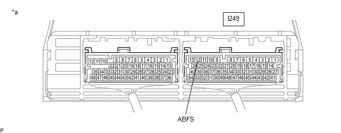
I249-12 (ABFS) - Body ground |
Ignition switch ON |
Below 1 V |
NOTICE:
Turning the ignition switch to ON with the airbag ECU assembly connector and the hybrid vehicle control ECU connector disconnected causes other DTCs to be stored. Clear the DTCs after performing this inspection.
(e) Turn the ignition switch off.
(f) Measure the resistance according to the value(s) in the table below.
Standard Resistance (Check for Open):
|
Tester Connection | Condition |
Specified Condition |
|---|---|---|
|
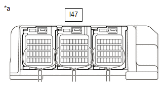
I249-12 (ABFS) - I47-24 (GSW2) |
Ignition switch off |
Below 1 Ω |
Standard Resistance (Check for Short):
|
Tester Connection | Condition |
Specified Condition |
|---|---|---|
|
I249-12 (ABFS) or I47-24 (GSW2) - Body ground and other terminals |
Ignition switch off |
10 kΩ or higher |
HINT:
As necessary, check that there are no wires shorted to power supply when performing the above wire harness inspection.
(g) Reconnect the airbag ECU assembly connector.
(h) Reconnect the hybrid vehicle control ECU connector.
| NG | | REPAIR OR REPLACE HARNESS OR CONNECTOR |
|
|
9. | CHECK HYBRID VEHICLE CONTROL ECU |
(a) Disconnect the airbag ECU assembly connector.
(b) Turn the ignition switch to ON.
(c) Measure the voltage according to the value(s) in the table below.
|
*a | Component with harness connected (Hybrid Vehicle Control ECU) |
- | - |
NOTICE:
Turning the ignition switch to ON with the airbag ECU assembly connector disconnected causes other DTCs to be stored. Clear the DTCs after performing this inspection.
Standard Voltage:
|
Tester Connection | Condition |
Specified Condition |
|---|---|---|
|
I249-12 (ABFS) - Body ground |
Ignition switch ON |
11 to 14 V |
(d) Turn the ignition switch off.
(e) Reconnect the airbag ECU assembly connector.
| NG | | REPLACE HYBRID VEHICLE CONTROL ECU |
|
|
10. | CHECK HARNESS AND CONNECTOR (AIRBAG ECU ASSEMBLY - BODY GROUND) |
(a) Disconnect the airbag ECU assembly connector.
(b) Measure the voltage according to the value(s) in the table below.
Standard Voltage:
|
Tester Connection | Condition |
Specified Condition |
|---|---|---|
|
I47-33 (E1) - Body ground |
Ignition switch off |
Below 1 Ω |
(c) Reconnect the airbag ECU assembly connector.
| OK | | REPLACE AIRBAG ECU ASSEMBLY |
| NG | | REPAIR OR REPLACE HARNESS OR CONNECTOR |
READ NEXT:
 Lost Communication with Airbag System Control Module Signal Plausibility Failure (P310764)
DESCRIPTION Refer to the description for DTC P310711.
Click here
DTC No. Detection Item
DTC Detection Condition
Trouble Area MIL
Warning Indicate Note
P310
Transmission (Shaft) Mechanical Linkage Failure (P314779)
DTC SUMMARY Refer to the DTC summary for DTC P1C7779.
Click here DESCRIPTION
Refer to the description for DTC P1C7779. Click here
DTC No. Detection Item
DTC Detection Condi
Motor Electronics Coolant Pump "A" No Signal (P314A31)
DESCRIPTION Refer to the description for DTC P0C7396.
Click here The inverter water pump assembly sends the inverter water pump speed (measured value) signal to the hybrid vehicle control ECU.
SEE MORE:
 Brake Pressure Control Solenoid "C" Control Circuit Short to Battery (C14F112,...,C14FA49)
DESCRIPTION
The ABS solenoid relay and reservoir cut solenoid valves are
built into the brake actuator assembly.
When the brakes are operating, the reservoir cut solenoid valves
supply brake fluid from the brake master cylinder reservoir assembly to the pump
motor as necessary.
When this DT
Wireless Charger Power Source Circuit
DESCRIPTION This is the power source circuit for the mobile wireless charger cradle assembly. WIRING DIAGRAM
CAUTION / NOTICE / HINT
NOTICE: Inspect the fuses for circuits related to this system before performing the following procedure. PROCEDURE
1.
CHECK HARNESS AND CONNECTOR (MOBI
