Toyota Corolla Cross: Intake Air Temperature Sensor 1 Bank 1 Circuit Short to Ground (P011011)
DESCRIPTION
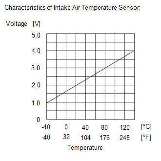
The intake air temperature sensor, mounted on the mass air flow meter sub-assembly, monitors the intake air temperature. The intake air temperature sensor has a built-in thermistor with a resistance that varies according to the temperature of the intake air. When the intake air temperature is low, the resistance of the thermistor increases. When the temperature is high, the resistance drops. These variations in resistance are transmitted to the ECM as voltage changes.
The intake air temperature detected by the inlet air temperature sensor is converted to a voltage value inside the intake airflow meter assembly, and the voltage value is then output to the ECM. Based on this signal, the ECM increases the fuel injection volume when the engine is cold to improve driveability.
HINT:
When DTC P011011 is stored, the ECM enters fail-safe mode. During fail-safe mode, the intake air temperature is estimated to be 20°C (68°F) by the ECM. Fail-safe mode continues until a pass condition is detected, and the ignition switch is then turned off.
|
DTC No. | Detection Item |
DTC Detection Condition | Trouble Area |
MIL | Note |
|---|---|---|---|---|---|
|
P011011 | Intake Air Temperature Sensor 1 Bank 1 Circuit Short to Ground |
The intake air temperature sensor output voltage is less than 0.176 V*1 or 0.146V*2 for 0.5 seconds or more (1 trip detection logic). |
| Comes on |
|
- *1: except Mexico models
- *2: for Mexico models
HINT:
When this DTC is output, check the intake air temperature in the Data List. Enter the following menus: Powertrain / Engine / Data List / Intake Air Temperature.
except Mexico Models|
DTC No. | Intake Air Temperature |
Malfunction |
|---|---|---|
| P011011 |
Higher than 128°C (262°F) |
Short to ground in THA circuit |
|
DTC No. | Intake Air Temperature |
Malfunction |
|---|---|---|
| P011011 |
Higher than 138°C (280°F) |
Short to ground in THA circuit |
If the Data List values are normal, it may be due to a temporary recovery from the malfunction condition. Check for intermittent problems.
Click here .gif)
MONITOR DESCRIPTION
The ECM monitors the sensor voltage and uses this value to calculate the intake air temperature. When the sensor output voltage deviates from the normal operating range, the ECM interprets this as a malfunction in the intake air temperature sensor (mass air flow meter sub-assembly) circuit, illuminates the MIL and stores a DTC.
Example:
If the intake air temperature sensor output voltage is less than 0.176 V*1 or 0.142 V*2 for 0.5 seconds or more, the ECM will illuminates the MIL and store this DTC.
- *1: except Mexico Models
- *2: for Mexico Models
MONITOR STRATEGY
|
Related DTCs | P0112: Intake air temperature sensor range check (low voltage) |
|
Required Sensors/Components (Main) | Intake air temperature sensor (mass air flow meter sub-assembly) |
|
Required Sensors/Components (Related) |
- |
| Frequency of Operation |
Continuous |
| Duration |
0.5 seconds |
| MIL Operation |
Immediate |
| Sequence of Operation |
None |
TYPICAL ENABLING CONDITIONS
|
Monitor runs whenever the following DTCs are not stored |
None |
| Both of the following conditions are met |
- |
| Auxiliary battery voltage |
8 V or higher |
| Ignition switch |
ON |
TYPICAL MALFUNCTION THRESHOLDS
|
Intake air temperature sensor voltage [Intake air temperature] |
Less than 0.176 V [Higher than 128°C (262°F)]: except Mexico Models Less than 0.142 V [Higher than 138°C (280°F)]: for Mexico Models |
CONFIRMATION DRIVING PATTERN
HINT:
- After repair has been completed, clear the DTC and then check that the vehicle has returned to normal by performing the following All Readiness check procedure.
Click here
- When clearing the permanent DTCs, refer to the "CLEAR PERMANENT DTC" procedure.
Click here
- Connect the GTS to the DLC3.
- Turn the ignition switch to ON.
- Turn the GTS on.
- Clear the DTCs (even if no DTCs are stored, perform the clear DTC procedure).
- Turn the ignition switch off and wait for at least 30 seconds.
- Turn the ignition switch to ON [A].
- Turn the GTS on.
- Wait 0.5 seconds or more [B].
- Enter the following menus: Powertrain / Engine / Trouble Codes [C].
- Read the pending DTCs.
HINT:
- If a pending DTC is output, the system is malfunctioning.
- If a pending DTC is not output, perform the following procedure.
- Enter the following menus: Powertrain / Engine / Utility / All Readiness.
- Input the DTC: P011011.
- Check the DTC judgment result.
GTS Display
Description
NORMAL
- DTC judgment completed
- System normal
ABNORMAL
- DTC judgment completed
- System abnormal
INCOMPLETE
- DTC judgment not completed
- Perform driving pattern after confirming DTC enabling conditions
HINT:
- If the judgment result is NORMAL, the system is normal.
- If the judgment result is ABNORMAL, the system is malfunctioning.
- [A] to [C]: Normal judgment procedure.
The normal judgment procedure is used to complete DTC judgment and also used when clearing permanent DTCs.
- When clearing the permanent DTCs, do not disconnect the cable from the auxiliary battery terminal or attempt to clear the DTCs during this procedure, as doing so will clear the universal trip and normal judgment histories.
WIRING DIAGRAM

CAUTION / NOTICE / HINT
NOTICE:
- Vehicle Control History may be stored in the hybrid vehicle control ECU assembly if the engine is malfunctioning. Certain vehicle condition information is recorded when Vehicle Control History is stored. Reading the vehicle conditions recorded in both the freeze frame data and Vehicle Control History can be useful for troubleshooting.
Click here
(Select Powertrain in Health Check and then check the time stamp data.)
- If any "Engine Malfunction" Vehicle Control History item has been stored in the hybrid vehicle control ECU assembly, make sure to clear it. However, as all Vehicle Control History items are cleared simultaneously, if any Vehicle Control History items other than "Engine Malfunction" are stored, make sure to perform any troubleshooting for them before clearing Vehicle Control History.
Click here
HINT:
Read Freeze Frame Data using the GTS. The ECM records vehicle and driving condition information as Freeze Frame Data the moment a DTC is stored. When troubleshooting, Freeze Frame Data can help determine if the vehicle was moving or stationary, if the engine was warmed up or not, if the air fuel ratio was lean or rich, and other data from the time the malfunction occurred.
PROCEDURE
| 1. |
CHECK HARNESS AND CONNECTOR |
|
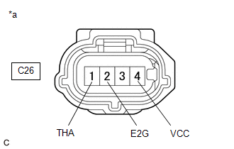
*a | Front view of wire harness connector (to Mass Air Flow Meter Sub-assembly) |
HINT:
Make sure that the connector is properly connected. If it is not, securely connect it and check for DTCs again.
(a) Disconnect the mass air flow meter sub-assembly connector.
(b) Turn the ignition switch to ON.
(c) Measure the voltage according to the value(s) in the table below.
Standard Voltage:
|
Tester Connection | Condition |
Specified Condition |
|---|---|---|
|
C26-4 (VCC) - C26-2 (E2G) |
Ignition switch ON | 4.8 to 5.2 V |
|
C26-1 (THA) - C26-2 (E2G) |
Ignition switch ON | 4.8 to 5.2 V |
(d) Turn the ignition switch off and wait for at least 30 seconds.
(e) Measure the resistance according to the value(s) in the table below.
Standard Resistance:
|
Tester Connection | Condition |
Specified Condition |
|---|---|---|
|
C26-4 (VCC) - C26-1 (THA) |
Ignition switch off | 2.565 to 2.835 kΩ |
HINT:
Perform "Inspection After Repair" after replacing the mass air flow meter sub-assembly.
Click here
| OK | .gif) | REPLACE MASS AIR FLOW METER SUB-ASSEMBLY |
|
.gif)
| 2. |
CHECK HARNESS AND CONNECTOR (MASS AIR FLOW METER SUB-ASSEMBLY - ECM) |
(a) Disconnect the mass air flow meter sub-assembly connector.
(b) Disconnect the ECM connector.
(c) Measure the resistance according to the value(s) in the table below.
Standard Resistance:
|
Tester Connection | Condition |
Specified Condition |
|---|---|---|
|
C26-4 (VCC) - C139-78 (VCVG) |
Always | Below 1 Ω |
|
C26-1 (THA) or C139-102 (THA) - Body ground and other terminals |
Always | 10 kΩ or higher |
| OK | | REPLACE ECM |
| NG | | REPAIR OR REPLACE HARNESS OR CONNECTOR |
READ NEXT:
 Intake Air Temperature Sensor 1 Bank 1 Circuit Short to Battery or Open (P011015)
DESCRIPTION Refer to DTC P011011. Click here
HINT: When DTC P011015 is stored, the ECM enters fail-safe mode. During fail-safe mode, the intake air temperature is estimated to be 20°C (68°F) by
Intake Air Temperature Sensor 1 Bank 1 Signal Stuck in Range (P01102A)
DESCRIPTION Refer to DTC P011011. Click here
DTC No. Detection Item
DTC Detection Condition Trouble Area
MIL Note
P01102A Intake Air Temperature Sensor 1 Bank 1 Sig
Engine Coolant Temperature Sensor 1 Circuit Short to Ground (P011511)
DESCRIPTION
A thermistor, whose resistance value varies according to the engine coolant temperature, is built into the engine coolant temperature sensor. The structure of the sensor and its connect
SEE MORE:
 Removal
REMOVAL CAUTION / NOTICE / HINT COMPONENTS (REMOVAL)
Procedure Part Name Code
1 REFRIGERANT FROM REFRIGERATION SYSTEM
-
- -
2 SERVICE PLUG GRIP
G3834 -
- -
3 CHECK TERMINAL VOLTAGE
-
Power Steering ECU Communication Stop Mode
DESCRIPTION
Detection Item
Symptom
Trouble Area
Power Steering ECU Communication Stop Mode
Communication stop for "Power Steering (EPS)" is indicated on the "Communication
Bus Check" screen of the GTS.
Click her
