Toyota Corolla Cross: Removal
REMOVAL
CAUTION / NOTICE / HINT
COMPONENTS (REMOVAL)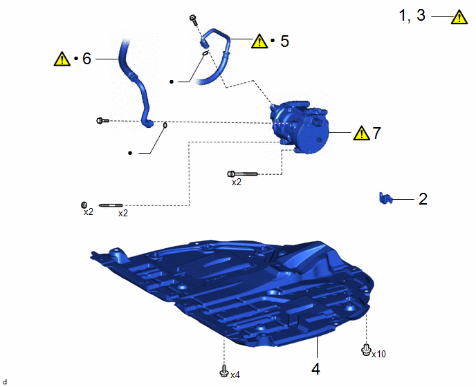
|
Procedure | Part Name Code |
.png) |
.png) |
 |
|---|---|---|---|---|---|
|
1 | REFRIGERANT FROM REFRIGERATION SYSTEM |
- |
|
- | - |
|
2 | SERVICE PLUG GRIP |
G3834 | - |
- | - |
|
3 | CHECK TERMINAL VOLTAGE |
- |
|
- | - |
|
4 | NO. 1 ENGINE UNDER COVER ASSEMBLY |
51410 | - |
- | - |
|
5 | DISCHARGE HOSE SUB-ASSEMBLY |
88703 |
|
- | - |
|
6 | SUCTION HOSE SUB-ASSEMBLY |
88704 |
|
- | - |
|
7 | COMPRESSOR WITH MOTOR ASSEMBLY |
88370 |
|
- | - |
|
● | Non-reusable part |
- | - |
CAUTION / NOTICE / HINT
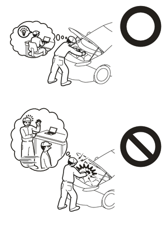
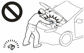
CAUTION:
- Orange wire harnesses and connectors indicate high-voltage circuits. To prevent electric shock, always follow the procedure described in the repair manual.
Click here
.gif)
- To prevent electric shock, wear insulated gloves when working on wire harnesses and components of the high voltage system.
NOTICE:
If metal dust is produced inside the cooler compressor assembly, it could cause a clog in the modulator. If any metal dust comes out, replace the cooler dryer inside the modulator also.
Click here
HINT:
When the cable is disconnected/reconnected to the auxiliary battery terminal, systems temporarily stop operating. However, each system has a function that completes learning the first time the system is used.
- Learning completes when vehicle is driven
Effect/Inoperative Function When Necessary Procedures are not Performed
Necessary Procedures
Link
Front Camera System
Drive the vehicle straight ahead at 15 km/h (10 mph) or more for 1 second or more.
- Learning completes when vehicle is operated normally
Effect/Inoperative Function When Necessary Procedures are not Performed
Necessary Procedures
Link
Power door lock control system
- Back door opener
Perform door unlock operation with door control switch or electrical key transmitter sub-assembly switch.
Power back door system
Fully close the back door by hand.
HINT:
Initialization is not necessary if the above procedures are performed while the back door is closed.
Air conditioning system
After the ignition switch is turned to ON, the servo motor standard position is recognized.
-
PROCEDURE
1. RECOVER REFRIGERANT FROM REFRIGERATION SYSTEM
Click here
2. REMOVE SERVICE PLUG GRIP
Click here
3. CHECK TERMINAL VOLTAGE
(a) Remove the connector cover assembly.
Click here
(b) Check the terminal voltage.
Click here
(c) Install the connector cover assembly.
Click here
4. REMOVE NO. 1 ENGINE UNDER COVER ASSEMBLY
Click here
5. DISCONNECT DISCHARGE HOSE SUB-ASSEMBLY

(1) Remove the bolt to disconnect the discharge hose sub-assembly from the compressor with motor assembly.
(2) Remove the O-ring from the discharge hose sub-assembly.
NOTICE:
Seal the openings of the disconnected parts using vinyl tape to prevent moisture and foreign matter from entering them.
6. DISCONNECT SUCTION HOSE SUB-ASSEMBLY
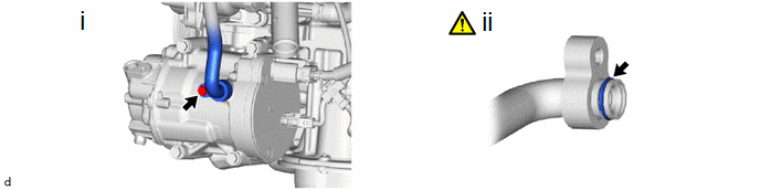
(1) Remove the bolt to disconnect the suction hose sub-assembly from the compressor with motor assembly.
(2) Remove the O-ring from the suction hose sub-assembly.
NOTICE:
Seal the openings of the disconnected parts using vinyl tape to prevent moisture and foreign matter from entering them.
7. REMOVE COMPRESSOR WITH MOTOR ASSEMBLY
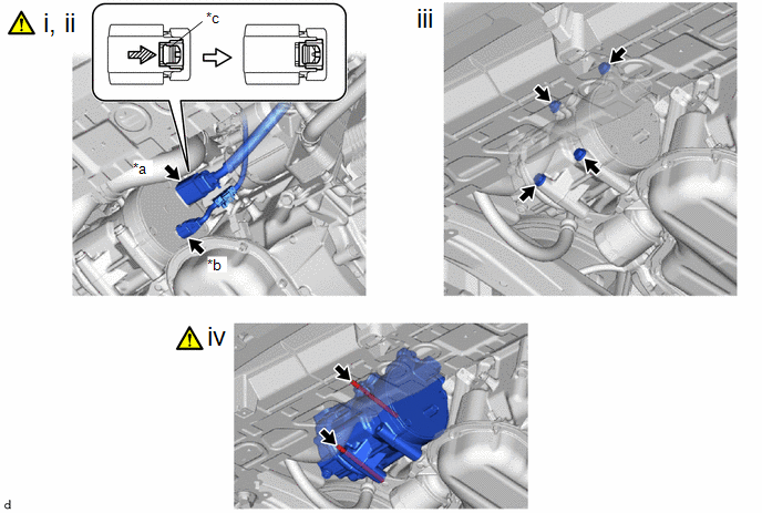
|
*a | Connector (A) |
*b | Connector (B) |
|
*c | Green-colored Lock |
- | - |
 |
Slide | - |
- |
(1) Using a screwdriver, slide the green-colored lock of the connector (A) as shown in the illustration to release it and disconnect the connector.
CAUTION:
Make sure to wear insulated gloves.
NOTICE:
Insulate the disconnected terminals and connector with insulating tape.
(2) Disconnect the connector (B).
(3) Remove the 2 bolts and 2 nuts.
(4) Using an E8 "TORX" socket wrench, remove the 2 stud bolts and compressor with motor assembly.


