Toyota Corolla Cross: Installation
INSTALLATION
CAUTION / NOTICE / HINT
COMPONENTS (INSTALLATION)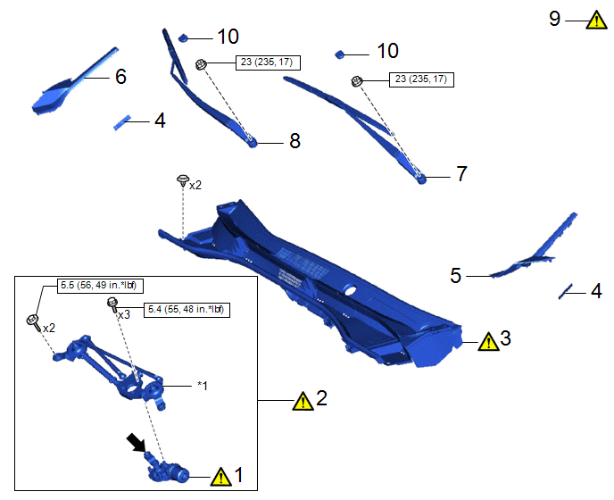
|
Procedure | Part Name Code |
.png) |
.png) |
 |
|---|---|---|---|---|---|
|
1 | WINDSHIELD WIPER MOTOR ASSEMBLY |
85110 |
|
- | - |
|
2 | WINDSHIELD WIPER MOTOR AND LINK ASSEMBLY |
- |
|
- | - |
|
3 | COWL TOP VENTILATOR LOUVER SUB-ASSEMBLY |
55708 |
|
- | - |
|
4 | WINDSHIELD OUTSIDE MOULDING CLIP |
75545M | - |
- | - |
|
5 | NO. 2 FRONT SIDE PANEL PROTECTOR LH |
53824D | - |
- | - |
|
6 | NO. 2 FRONT SIDE PANEL PROTECTOR RH |
53823G | - |
- | - |
|
7 | FRONT WIPER ARM AND BLADE ASSEMBLY LH |
- | - |
- | - |
|
8 | FRONT WIPER ARM AND BLADE ASSEMBLY RH |
- | - |
- | - |
|
9 | INSPECT FRONT WIPER ARM AND BLADE ASSEMBLY |
- |
|
- | - |
|
10 | FRONT WIPER ARM HEAD CAP |
85292B | - |
- | - |
|
*1 | WINDSHIELD WIPER LINK ASSEMBLY |
- | - |
.png) |
N*m (kgf*cm, ft.*lbf): Specified torque |
.png) |
MP grease |
CAUTION / NOTICE / HINT
NOTICE:
Make sure to hold the front wiper arm while lifting it, as lifting the front wiper arm by the front wiper blade may damage or deform the front wiper blade.
PROCEDURE
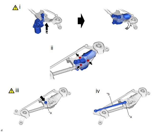
1. INSTALL WINDSHIELD WIPER MOTOR ASSEMBLY
|
*a | Pivot of Windshield Wiper Motor Assembly |
*b | No. 1 Windshield Wiper Link Rod |
.png) |
Install in this Direction (1) |
.png) |
Install in this Direction (2) |
|
|
MP grease | - |
- |
(1) Temporarily install the windshield wiper motor assembly to the wiper link assembly as shown in the illustration.
(2) Install the windshield wiper motor assembly with the 3 bolts.
Torque:
5.4 N·m {55 kgf·cm, 48 in·lbf}
(3) Apply MP grease to the pivot of the windshield wiper motor assembly.
(4) Install the No. 1 windshield wiper link rod to the pivot of the windshield wiper motor assembly.
2. INSTALL WINDSHIELD WIPER MOTOR AND LINK ASSEMBLY
|
|
NOTICE: Be careful not to damage the windshield glass when installing the windshield wiper motor and link assembly. |
Torque:
5.5 N·m {56 kgf·cm, 49 in·lbf}
3. INSTALL COWL TOP VENTILATOR LOUVER SUB-ASSEMBLY
|
|
NOTICE: When installing the cowl top ventilator louver sub-assembly, it may contact the brake master cylinder reservoir filler cap assembly and cause it to fall off. Check the installation condition of the brake master cylinder reservoir filler cap assembly after installing the cowl top ventilator louver sub-assembly. |
4. INSTALL WINDSHIELD OUTSIDE MOULDING CLIP

(b) Use the same procedure for the RH side and LH side.
5. INSTALL NO. 2 FRONT SIDE PANEL PROTECTOR LH
6. INSTALL NO. 2 FRONT SIDE PANEL PROTECTOR RH
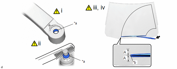
7. INSTALL FRONT WIPER ARM AND BLADE ASSEMBLY LH
|
*a | Serration |
*b | Alignment Mark |
(1) When reusing the front wiper arm and blade assembly LH:
1. Clean the front wiper arm serrations to remove any burrs, dirt, etc.
NOTICE:
Do not grind down the wiper arm serrations.
(2) When reusing the windshield wiper motor and link assembly:
1. Clean the wiper pivot serrations with a wire brush.
NOTICE:
Do not grind down the wiper pivot serrations.
(3) Set the automatic stop position by the below procedure.
1. Turn the ignition switch ON.
2. Operate the windshield wiper motor assembly and stop the windshield wiper motor and link assembly at the automatic stop position.
3. Turn the ignition switch off.
(4) Install the front wiper arm and blade assembly LH with the nut to the position shown in the illustration.
HINT:
Hold the wiper arm by hand while tightening the nut.
Torque:
23 N·m {235 kgf·cm, 17 ft·lbf}
Reference Measurement:
|
Area | Measurement |
Area | Measurement |
|---|---|---|---|
|
A | 10 mm (0.394 in.) |
- | - |
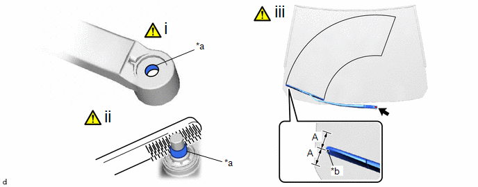
8. INSTALL FRONT WIPER ARM AND BLADE ASSEMBLY RH
|
*a | Serration |
*b | Alignment Mark |
(1) When reusing the front wiper arm and blade assembly RH:
1. Clean the front wiper arm serrations to remove any burrs, dirt, etc.
NOTICE:
Do not grind down the wiper arm serrations.
(2) When reusing the windshield wiper motor and link assembly:
1. Clean the wiper pivot serrations with a wire brush.
NOTICE:
Do not grind down the wiper pivot serrations.
(3) Install the front wiper arm and blade assembly RH with the nut to the position as shown in the illustration.
HINT:
Hold the wiper arm by hand while tightening the nut.
Torque:
23 N·m {235 kgf·cm, 17 ft·lbf}
Reference Measurement:
|
Area | Measurement |
Area | Measurement |
|---|---|---|---|
|
A | 10 mm (0.394 in.) |
- | - |
9. INSPECT FRONT WIPER ARM AND BLADE ASSEMBLY
Click here
.gif)
10. INSTALL FRONT WIPER ARM HEAD CAP


