Toyota Corolla Cross: Removal
REMOVAL
CAUTION / NOTICE / HINT
COMPONENTS (REMOVAL).png)
|
Procedure | Part Name Code |
.png) |
.png) |
 |
|---|---|---|---|---|---|
|
1 | UPPER BACK DOOR TRIM PANEL ASSEMBLY |
64790B | - |
- | - |
|
2 | BACK DOOR SIDE GARNISH LH |
67938A | - |
- | - |
|
3 | BACK DOOR SIDE GARNISH RH |
67937B | - |
- | - |
|
4 | BACK DOOR TRIM PANEL ASSEMBLY |
64780A | - |
- | - |

|
Procedure | Part Name Code |
.png) |
.png) |
 |
|---|---|---|---|---|---|
|
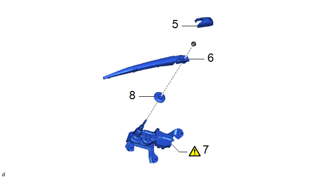
5 | REAR WIPER ARM HEAD CAP |
85292A | - |
- | - |
|
6 | REAR WIPER ARM AND BLADE ASSEMBLY |
- | - |
- | - |
|
7 | REAR WIPER MOTOR ASSEMBLY |
85110R |
|
- | - |
|
8 | REAR WIPER MOTOR GROMMET |
85143R | - |
- | - |
PROCEDURE
1. REMOVE UPPER BACK DOOR TRIM PANEL ASSEMBLY
Click here
.gif)
.gif)
2. REMOVE BACK DOOR SIDE GARNISH LH
Click here .gif)
.gif)
3. REMOVE BACK DOOR SIDE GARNISH RH
(a) Use the same procedure as for the LH side.
4. REMOVE BACK DOOR TRIM PANEL ASSEMBLY
Click here
.gif)
.gif)
5. REMOVE REAR WIPER ARM HEAD CAP

.png) |
Remove in this Direction |
- | - |
6. REMOVE REAR WIPER ARM AND BLADE ASSEMBLY

7. REMOVE REAR WIPER MOTOR ASSEMBLY

(1) Disconnect the connector.
(2) Loosen the 3 bolts to remove the rear wiper motor assembly.
HINT:
Remove the 3 bolt and rear wiper motor assembly as a set.
8. REMOVE REAR WIPER MOTOR GROMMET


