Toyota Corolla Cross: Installation
INSTALLATION
CAUTION / NOTICE / HINT
COMPONENTS (INSTALLATION)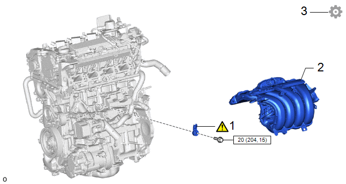
|
Procedure | Part Name Code |
.png) |
.png) |
 |
|---|---|---|---|---|---|
|
1 | KNOCK CONTROL SENSOR |
89615 |
|
- | - |
|
2 | INTAKE MANIFOLD |
17111 | - |
- | - |
|
3 | PERFORM INITIALIZATION |
- | - |
- |
|
.png) |
N*m (kgf*cm, ft.*lbf): Specified torque |
- | - |
CAUTION / NOTICE / HINT
NOTICE:
This procedure includes the installation of small-head bolts. Refer to Small-Head Bolts of Basic Repair Hint to identify the small-head bolts.
Click here .gif)
PROCEDURE
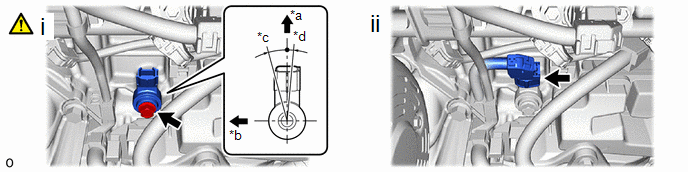
1. INSTALL KNOCK CONTROL SENSOR
|
|
HINT: Perform "Inspection After Repair" after replacing the knock control sensor. Click here |
|
*a | Top of Vehicle |
*b | Right of Vehicle |
|
*c | 15° |
*d | 5° |
(1) Install the knock control sensor to the cylinder block sub-assembly with the bolt so that the knock control sensor installation position is as shown in the illustration.
Torque:
20 N·m {204 kgf·cm, 15 ft·lbf}
NOTICE:
- If the knock control sensor has been struck or dropped, replace it.
- Make sure that the knock control sensor is in the correct position.
(2) Connect the knock control sensor connector.
2. INSTALL INTAKE MANIFOLD
Click here
3. PERFORM INITIALIZATION
(a) Perform "Inspection After Repair" after replacing the knock control sensor.
Click here


