Toyota Corolla Cross: Inspection
INSPECTION
PROCEDURE
1. INSPECT FUEL SENDER GAUGE ASSEMBLY
CAUTION:
Perform the inspection in a well-ventilated area.
Do not perform the inspection near an open flame.
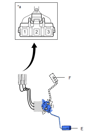
(a) Check that the float moves smoothly between F and E.
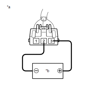
(b) Check the fuel sender gauge assembly voltage.
| (1) Apply 5 V between terminals 2 and 3.
NOTICE:
- Be careful when connecting the leads, as the fuel sender gauge assembly may be damaged if the leads are connected to the wrong terminals.
- Do not apply more than 6 V to terminals 2 or 3.
HINT: If a stable power supply is not available, connect 4 nickel-metal hydride batteries (1.2 V each) or equivalent in series. |
 |
|
*a | Component without harness connected
(Fuel Sender Gauge Assembly) | |
*b | Voltage Applied between Terminals | | |
| (2) Measure the voltage according to the value(s) in the table below.
Standard Voltage: |
Tester Connection | Float Level |
Specified Condition | |
1 - 2 | F |
4.255 to 4.605 V* | |
Between F and E | 0.345 to 4.605 V* (Gradually changes) | |
E | 0.345 to 0.695 V* |
*: The output voltage changes depending on the voltage applied to the terminals.
Output voltage (F) = (0.851 x Voltage applied to terminals) to (0.921 x Voltage applied to terminals)
Output voltage (E) = (0.069 x Voltage applied to terminals) to (0.139 x Voltage applied to terminals)
If the result is not as specified, replace the fuel sender gauge assembly. |
 |
|
*a | Component without harness connected
(Fuel Sender Gauge Assembly) | | |
READ NEXT:
INSTALLATION CAUTION / NOTICE / HINT COMPONENTS (INSTALLATION)
Procedure Part Name Code
1 FUEL SENDER GAUGE ASSEMBLY
83320
- -
2
REMOVAL CAUTION / NOTICE / HINT COMPONENTS (REMOVAL)
Procedure Part Name Code
1 FUEL SUCTION WITH PUMP AND GAUGE TUBE ASSEMBLY
77020A -
- -
SEE MORE:
INSPECTION PROCEDURE 1. INSPECT SPIRAL CABLE SUB-ASSEMBLY
NOTICE:
Do not remove the steering sensor from the spiral cable sub-assembly when inspecting the spiral cable sub-assembly.
Remove the steering sensor from the spiral cable sub-assembly only when replacing the spiral cable sub-asse
REPLACEMENT
CAUTION / NOTICE / HINT
The necessary procedures (adjustment, calibration, initialization, or registration)
that must be performed after parts are removed and installed, or replaced during
the CVT fluid replacement are shown below.
Necessary Procedure After Parts Removed/Installed


