Toyota Corolla Cross: Inspection
INSPECTION
PROCEDURE
1. INSPECT FUEL PRESSURE SENSOR
(a) Check the fuel pressure sensor output voltage.
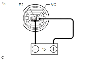
| (1) Apply 5 V between terminals 1 (VC) and 2 (E2).
NOTICE:
- Be careful when connecting the leads as the fuel pressure sensor may be damaged if the leads are connected to the wrong terminals.
- Do not apply more than 6 V to terminals 1 (VC) or 2 (E2).
HINT: If a stable power supply is not available, connect 4 nickel-metal hydride batteries (1.2 V each) or equivalent in series. |
 |
|
*a | Component without harness connected
(Fuel Pressure Sensor) | |
*b | Voltage Applied between Terminals | | |
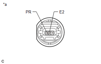
| (2) Measure the voltage according to the value(s) in the table below.
Standard Voltage: |
Tester Connection | Condition |
Specified Condition | |
3 (PR) - 2 (E2) | Pressure not applied to fuel pressure sensor |
Approximately 0.4 to 0.6 V* | *: The output voltage changes depending on the voltage applied to the terminals.
If the result is not as specified, replace the fuel pressure sensor. |
 |
|
*a | Component without harness connected
(Fuel Pressure Sensor) | | |
READ NEXT:
INSTALLATION CAUTION / NOTICE / HINT COMPONENTS (INSTALLATION)
Procedure Part Name Code
1 FUEL PRESSURE SENSOR
89458
- -
2 NO. 1
REMOVAL CAUTION / NOTICE / HINT COMPONENTS (REMOVAL)
Procedure Part Name Code
1 PRECAUTION
-
- -
2 DISCHARGE FUEL SYSTEM PRESSUR
SEE MORE:
INSTALLATION CAUTION / NOTICE / HINT COMPONENTS (INSTALLATION)
Procedure Part Name Code
1 FRONT SEAT CUSHION HEATER ASSEMBLY
87510N -
- -
2 SEPARATE TYPE FRONT SEAT CUSHION COVER
71071S
- -
*1 SEPARATE
DATA LIST / ACTIVE TEST DATA LIST NOTICE:
In the table below, the values listed under "Normal Condition" are reference values. Do not depend solely on these reference values when deciding whether a part is faulty or not.
HINT: Using the GTS to read the Data List allows the values or states of sw


