Toyota Corolla Cross: Initialization
INITIALIZATION
Inspection After Repair
Perform Learning Value Reset and Idle Learning after replacing or servicing parts related to engine operation. Details on procedures required are indicated by an asterisk and a number, and are explained in detail following the table.
|
Part Replaced | Engine Operation |
Learning Value Reset*1 | Idle Learning*2 |
|---|---|---|---|
| - |
○ | ○ |
| - |
○ | ○ |
|
Engine assembly | - |
○ | ○ |
| Confirm the following and perform Learning Value Reset and Idle Learning when one or more of the following conditions is met:
| ○ |
○ |
| The none of the conditions in the list above are met. |
- | - | |
|
Knock control sensor*4 |
- | - |
- |
- ○: Necessary.
- -: Unnecessary.
NOTICE:
Engine learned values cannot be reset by disconnecting the cable from the negative (-) auxiliary battery terminal or removing the EFI NO. 1 fuse.
- *1: Learning Value Reset
- Connect the GTS to the DLC3.
- Turn the ignition switch to ON.
- Turn the GTS on.
- Enter the following menus: Powertrain / Engine / Utility / Learning Value Reset.
- Confirm the following conditions as instructed on the screen.
- - Ignition switch ON
- - Engine stopped
- - Auxiliary battery voltage is higher than 9 V
- After confirming, select "Next" and initialize the learned value.
HINT:
If a message indicating learned value initialization failure is displayed on the screen, confirm the execution conditions, and perform learned value initialization again.
- After the completion of learned value initialization, confirm the air fuel ratio learned values (A/F Learn Value Idle (Port) Bank 1, A/F Learn Value Low (Port) Bank 1, A/F Learn Value Mid No.1 (Port) Bank 1, A/F Learn Value Mid No.2 (Port) Bank 1, A/F Learn Value High (Port) Bank 1, A/F Learn Value Idle Bank 1, A/F Learn Value Low Bank 1, A/F Learn Value Mid No.1 Bank 1, A/F Learn Value Mid No.2 Bank 1 and A/F Learn Value High Bank 1) in the Data List.
If 0 is displayed for all of the air fuel ratio learned values, initialization has completed correctly.
If a value other than 0 is displayed for one of the air fuel ratio learned values, perform initialization again. After initialization, confirm the air fuel ratio learned values. If a value other than 0 is displayed, replace the ECM.
- *2: Idle Learning
- Turn the ignition switch off and wait for at least 30 seconds.
- Start the engine and warm it up with the air conditioning and all accessories off, until the engine coolant temperature is 80°C (176°F) or higher.
HINT:
Learning starts when the engine coolant temperature is 80°C (176°F) or higher.
- After the engine is warmed up, allow it to idle for 5 minutes with the air conditioning and all accessories off.
- Confirm that the idle speed is within the standard range.
Standard:
Engine Idle Speed
750 to 850 rpm
HINT:
- Be sure to perform this step with the A/C switch and all accessories off.
- Make sure that the shift lever is in P.
- *3: Perform Learning Value Reset and Idle Learning after replacing the throttle body with motor assembly or cleaning deposits from the throttle body with motor assembly.
After that, check the idle speed. If the idle speed is out of the specified range, perform the following procedure.
CAUTION:
When performing the confirmation driving pattern, obey all speed limits and traffic laws.
HINT:
History information for driving and stopping is necessary to update Idle Learning.
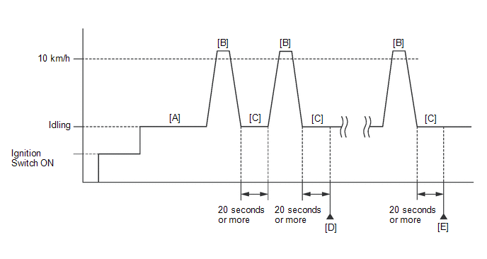
- Warm up the engine (engine coolant temperature of 80°C (176°F) or higher) with the A/C switch and all accessories off [A].
- Drive the vehicle at a speed of 10 km/h (6 mph) or more [B].
- Idle the engine for 20 seconds or more [C].
- Repeat procedure [B] and [C], and check that the idle speed is within the specified range [D].
Standard:
Engine Idle Speed
750 to 850 rpm
HINT:
- Be sure to perform this step with the A/C switch and all accessories off.
- Make sure that the shift lever is in P.
- If the idle speed is still out of the specified range, repeat procedure [B] and [C] until the idle speed is within the specified range [E].
- *4: Drive the vehicle for a short while after replacing the knock control sensor, and check if knocking occurs. If knocking occurs, drive the vehicle until knocking stops.


