Toyota Corolla Cross: Left Rear Wheel Speed Sensor Circuit Short to Ground or Open (C050C14)
DESCRIPTION
Refer to DTC C050C12
Click here .gif)
|
DTC No. |
Detection Item |
DTC Detection Condition |
Trouble Area |
|---|---|---|---|
|
C050C14 |
Left Rear Wheel Speed Sensor Circuit Short to Ground or Open |
A short or open circuit is detected in the speed sensor signal circuit for 0.12 seconds or more. |
|
- *1: for AWD
- *2: for 2WD
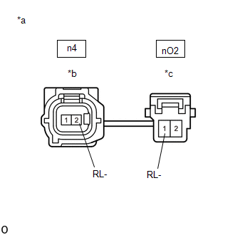
WIRING DIAGRAM
Refer to DTC C050C12.
Click here
PROCEDURE
|
1. |
CHECK VEHICLE |
(a) Check the vehicle specification.
|
Result |
Proceed to |
|---|---|
|
for 2WD |
A |
|
for AWD |
B |
| B | .gif)
|
GO TO STEP 7 |
|
.gif)
|
2. |
CHECK HARNESS AND CONNECTOR (SENSOR GROUND CIRCUIT) |
|
(a) Make sure that there is no looseness at the locking part and the connecting part of the connectors. OK: The connector is securely connected. |
|
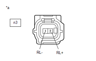
(b) Disconnect the n3 rear speed sensor LH (rear axle hub and bearing assembly LH) connector.
(c) Check both the connector case and the terminals for deformation and corrosion.
OK:
No deformation or corrosion.
(d) Turn the ignition switch to ON.
(e) Measure the voltage according to the value(s) in the table below.
Standard Voltage:
|
Tester Connection |
Condition |
Specified Condition |
|---|---|---|
|
n3-2 (RL+) - n3-1 (RL-) |
Ignition switch ON |
11 to 14 V |
| NG |
|
GO TO STEP 5 |
|
|
3. |
INSPECT NO. 2 PARKING BRAKE WIRE ASSEMBLY |
|
(a) Make sure that there is no looseness at the locking part and the connecting part of the connectors. OK: The connector is securely connected. |
|
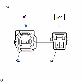
(b) Disconnect the n3 skid control sensor wire LH (No. 2 parking brake wire assembly) connector.
(c) Disconnect the nO2 skid control sensor wire LH (No. 2 parking brake wire assembly) connector.
(d) Check both the connector case and the terminals for deformation and corrosion.
OK:
No deformation or corrosion.
(e) Measure the resistance according to the value(s) in the table below.
Standard Resistance:
|
Tester Connection |
Condition |
Specified Condition |
|---|---|---|
|
n3-1 (RL-) or nO2-1 (RL-) - Body ground and other terminals |
Always |
10 kΩ or higher |
| NG |
|
REPLACE NO. 2 PARKING BRAKE WIRE ASSEMBLY |
|
|
4. |
CHECK HARNESS AND CONNECTOR (NO. 2 PARKING BRAKE WIRE ASSEMBLY - BRAKE ACTUATOR ASSEMBLY) |
(a) Make sure that there is no looseness at the locking part and the connecting part of the connectors.
OK:
The connector is securely connected.
(b) Disconnect the A151 skid control ECU (brake actuator assembly) connector.
(c) Disconnect the nO2 skid control sensor wire LH (No. 2 parking brake wire assembly) connector.
(d) Check both the connector case and the terminals for deformation and corrosion.
OK:
No deformation or corrosion.
(e) Measure the resistance according to the value(s) in the table below.
Standard Resistance:
|
Tester Connection |
Condition |
Specified Condition |
|---|---|---|
|
nO2-1 (RL-) or A151-23 (RL-) - Body ground |
Always |
10 kΩ or higher |
| OK |
|
REPLACE REAR AXLE HUB AND BEARING ASSEMBLY LH |
| NG |
|
REPAIR OR REPLACE HARNESS OR CONNECTOR |
|
5. |
INSPECT NO. 2 PARKING BRAKE WIRE ASSEMBLY |
|
(a) Make sure that there is no looseness at the locking part and the connecting part of the connectors. OK: The connector is securely connected. |
|
(b) Disconnect the n3 skid control sensor wire LH (No. 2 parking brake wire assembly) connector.
(c) Disconnect the nO2 skid control sensor wire LH (No. 2 parking brake wire assembly) connector.
(d) Check both the connector case and the terminals for deformation and corrosion.
OK:
No deformation or corrosion.
(e) Measure the resistance according to the value(s) in the table below.
Standard Resistance:
|
Tester Connection |
Condition |
Specified Condition |
|---|---|---|
|
n3-1 (RL-) - nO2-1 (RL-) |
Always |
Below 1 Ω |
| NG |
|
REPLACE NO. 2 PARKING BRAKE WIRE ASSEMBLY |
|
|
6. |
CHECK HARNESS AND CONNECTOR (NO. 2 PARKING BRAKE WIRE ASSEMBLY - BRAKE ACTUATOR ASSEMBLY) |
(a) Make sure that there is no looseness at the locking part and the connecting part of the connectors.
OK:
The connector is securely connected.
(b) Disconnect the A151 skid control ECU (brake actuator assembly) connector.
(c) Disconnect the nO2 skid control sensor wire LH (No. 2 parking brake wire assembly) connector.
(d) Check both the connector case and the terminals for deformation and corrosion.
OK:
No deformation or corrosion.
(e) Measure the resistance according to the value(s) in the table below.
Standard Resistance:
|
Tester Connection |
Condition |
Specified Condition |
|---|---|---|
|
nO2-1 (RL-) - A151-23 (RL-) |
Always |
Below 1 Ω |
| OK |
|
REPLACE BRAKE ACTUATOR ASSEMBLY |
| NG |
|
REPAIR OR REPLACE HARNESS OR CONNECTOR |
|
7. |
CHECK HARNESS AND CONNECTOR (SENSOR GROUND CIRCUIT) |
|
(a) Make sure that there is no looseness at the locking part and the connecting part of the connectors. OK: The connector is securely connected. |
|
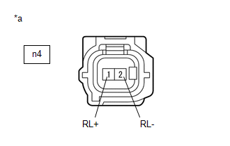
(b) Disconnect the n4 rear speed sensor LH connector.
(c) Check both the connector case and the terminals for deformation and corrosion.
OK:
No deformation or corrosion.
(d) Turn the ignition switch to ON.
(e) Measure the voltage according to the value(s) in the table below.
Standard Voltage:
|
Tester Connection |
Condition |
Specified Condition |
|---|---|---|
|
n4-1 (RL+) - n4-2 (RL-) |
Ignition switch ON |
11 to 14 V |
| NG |
|
GO TO STEP 5 |
|
|
8. |
INSPECT NO. 2 PARKING BRAKE WIRE ASSEMBLY |
|
(a) Make sure that there is no looseness at the locking part and the connecting part of the connectors. OK: The connector is securely connected. |
|
(b) Disconnect the n4 skid control sensor wire LH (No. 2 parking brake wire assembly) connector.
(c) Disconnect the nO2 skid control sensor wire LH (No. 2 parking brake wire assembly) connector.
(d) Check both the connector case and the terminals for deformation and corrosion.
OK:
No deformation or corrosion.
(e) Measure the resistance according to the value(s) in the table below.
Standard Resistance:
|
Tester Connection |
Condition |
Specified Condition |
|---|---|---|
|
n4-2 (RL-) or nO2-1 (RL-) - Body ground and other terminals |
Always |
10 kΩ or higher |
| NG |
|
REPLACE NO. 2 PARKING BRAKE WIRE ASSEMBLY |
|
|
9. |
CHECK HARNESS AND CONNECTOR (NO. 2 PARKING BRAKE WIRE ASSEMBLY - BRAKE ACTUATOR ASSEMBLY) |
(a) Make sure that there is no looseness at the locking part and the connecting part of the connectors.
OK:
The connector is securely connected.
(b) Disconnect the A151 skid control ECU (brake actuator assembly) connector.
(c) Disconnect the nO2 skid control sensor wire LH (No. 2 parking brake wire assembly) connector.
(d) Check both the connector case and the terminals for deformation and corrosion.
OK:
No deformation or corrosion.
(e) Measure the resistance according to the value(s) in the table below.
Standard Resistance:
|
Tester Connection |
Condition |
Specified Condition |
|---|---|---|
|
nO2-1 (RL-) or A151-23 (RL-) - Body ground |
Always |
10 kΩ or higher |
| OK |
|
REPLACE REAR SPEED SENSOR LH |
| NG |
|
REPAIR OR REPLACE HARNESS OR CONNECTOR |
READ NEXT:
 Left Rear Wheel Speed Sensor Circuit Voltage Out of Range (C050C1C)
DESCRIPTION
Refer to DTC C050C12
Click here
DTC No.
Detection Item
DTC Detection Condition
Trouble Area
C050C1C
Left Rear W
Left Rear Wheel Speed Sensor Circuit Intermittent (C050C1F)
DESCRIPTION
Refer to DTC C050C12
Click here
DTC No.
Detection Item
DTC Detection Condition
Trouble Area
C050C1F
Left Rear W
Left Rear Wheel Speed Sensor Signal Stuck Low (C050C23)
DESCRIPTION
Refer to DTC C050C12
Click here
DTC No.
Detection Item
DTC Detection Condition
Trouble Area
C050C23
Left Rear W
SEE MORE:
 Check Bus 3 Line
DESCRIPTION
Symptom
Trouble Area
There are ECUs or sensors that display a communication stop on the bus
diagnostic screen. Or, there are ECUs or sensors that store a communication
stop history on the "Detail" screen.
CAN main
A/C Inverter High Voltage Power Resource Circuit Voltage Out of Range (B14711C)
DESCRIPTION The hybrid vehicle control ECU monitors the voltage of the HV battery. The hybrid vehicle control ECU stops compressor control and stores this DTC when the monitored voltage is outside the specified range.
This DTC will be stored as a history DTC. Compressor control may not resume unle
