Toyota Corolla Cross: Ignition Switch On/Start Position Circuit Low Circuit Short to Ground or Open (P253314)
DESCRIPTION
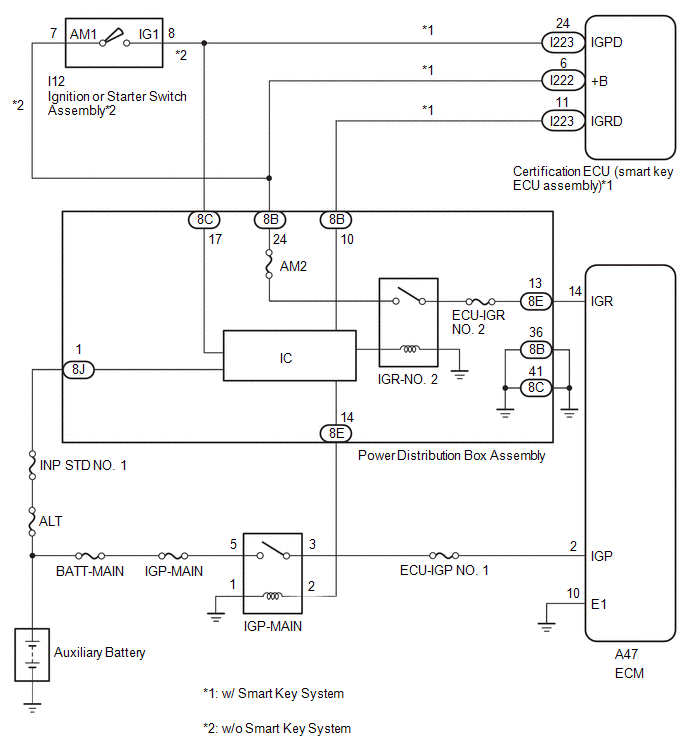
When the ignition switch is turned to ON, the auxiliary battery power source is supplied to the IGP and IGR terminals of the ECM. When the ignition switch is off, the auxiliary battery power source is cut off.
When the ignition switch is turned off during driving, the auxiliary battery power source supplied to the IGP terminal is cut off. However, the auxiliary battery power source supplied to the IGR terminal is supplied until the vehicle is stopped*1 or until the vehicle is stopped and the ignition switch is turned off*2.
*1: w/o Smart Key System
*2: w/ Smart Key System
|
DTC No. | Detection Item |
DTC Detection Condition | Trouble Area |
MIL | Note |
|---|---|---|---|---|---|
|
P253314 | Ignition Switch On/Start Position Circuit Low Circuit Short to Ground or Open |
Short to ground or open in IGR terminal circuit (2 trip detection logic). |
| - |
SAE: P2534 |
MONITOR DESCRIPTION
The ECM stores a DTC when there is no auxiliary battery voltage to the IGR terminal even though there is auxiliary battery voltage to the IGP terminal.
WIRING DIAGRAM
CONFIRMATION DRIVING PATTERN
- Connect the GTS to the DLC3.
- Turn the ignition switch to ON.
- Turn the GTS on.
- Clear the DTCs (even if no DTCs are stored, perform the clear DTC procedure).
- Turn the ignition switch off and wait for at least 30 seconds.
- Turn the ignition switch to ON.
- Turn the GTS on.
- Wait 1 minute or more.
- Enter the following menus: Powertrain / Engine / Trouble Codes.
- Read the pending DTCs.
HINT:
- If a pending DTC is output, the system is malfunctioning.
- If a pending DTC is not output, perform the following procedure.
- Enter the following menus: Powertrain / Engine / Utility / All Readiness.
- Input the DTC: P253314
- Check the DTC judgment result.
GTS Display
Description
NORMAL
- DTC judgment completed
- System normal
ABNORMAL
- DTC judgment completed
- System abnormal
INCOMPLETE
- DTC judgment not completed
- Perform driving pattern after confirming DTC enabling conditions
HINT:
- If the judgment result shows NORMAL, the system is normal.
- If the judgment result shows ABNORMAL, the system is malfunctioning.
CAUTION / NOTICE / HINT
HINT:
Read freeze frame data using the GTS. The ECM records vehicle and driving condition information as freeze frame data the moment a DTC is stored. When troubleshooting, freeze frame data can help determine if the vehicle was moving or stationary, if the engine was warmed up or not, if the air fuel ratio was lean or rich, and other data from the time the malfunction occurred.
PROCEDURE
| 1. |
READ VALUE USING GTS (IGR) |
(a) Read the Data List.
Powertrain > Engine > Data List|
Tester Display |
|---|
| IGR |
|
Result | Proceed to |
|---|---|
|
The value of IGR is ON |
A |
| None of the above conditions are met |
B |
| A |
.gif) | CHECK FOR INTERMITTENT PROBLEMS |
|
.gif)
| 2. |
CHECK TERMINAL VOLTAGE (IGR VOLTAGE) |
(a) Disconnect the ECM connector.
(b) Turn the ignition switch to ON.
(c) Measure the voltage according to the value(s) in the table below.
Standard Voltage:
|
Tester Connection | Condition |
Specified Condition |
|---|---|---|
|
A47-14 (IGR) - Body ground |
Ignition switch ON | 11 to 14 V |
| OK | | REPLACE ECM
|
.gif)
|
| 3. |
CHECK HARNESS AND CONNECTOR (POWER DISTRIBUTION BOX ASSEMBLY - ECM) |
(a) Disconnect the ECM connector.
(b) Disconnect the power distribution box assembly connector.
(c) Measure the resistance according to the value(s) in the table below.
Standard Resistance:
|
Tester Connection | Condition |
Specified Condition |
|---|---|---|
|
8E-13 - A47-14 (IGR) |
Always | Below 1 Ω |
|
8E-13 or A47-14 (IGR) - Body ground and other terminals |
Always | 10 kΩ or higher |
| NG | | REPAIR OR REPLACE HARNESS OR CONNECTOR |
|
| 4. |
CHECK HARNESS AND CONNECTOR (POWER DISTRIBUTION BOX ASSEMBLY - BODY GROUND) |
(a) Disconnect the power distribution box assembly connector.
(b) Measure the resistance according to the value(s) in the table below.
Standard Resistance:
|
Tester Connection | Condition |
Specified Condition |
|---|---|---|
|
8B-36 - Body ground | Always |
Below 1 Ω |
|
8C-41 - Body ground | Always |
Below 1 Ω |
| OK | | REPLACE POWER DISTRIBUTION BOX ASSEMBLY |
| NG | | REPAIR OR REPLACE HARNESS OR CONNECTOR |
READ NEXT:
 ECM/PCM Engine Off Timer Performance Signal Invalid (P261029,P261093)
DTC SUMMARY
DTC No. Detection Item
DTC Detection Condition Trouble Area
MIL Note
P261029 ECM/PCM Engine Off Timer Performance Signal Invalid
ECM internal malfunct
Camshaft Position Signal Output "A" General Electrical Failure (P261401)
DESCRIPTION Refer to DTC P001001. Click here
DTC No. Detection Item
DTC Detection Condition Trouble Area
MIL Note
P261401 Camshaft Position Signal Output "A" Genera
Engine Coolant Bypass Valve Circuit Short to Ground (P268111,P268115)
DESCRIPTION The flow shutting valve (for heater control) used for the variable cooling system is a magnet type valve that is closed when the engine is warming up to prevent coolant from flowing throug
SEE MORE:
 Power Back Door Touch Sensor
RemovalREMOVAL CAUTION / NOTICE / HINT COMPONENTS (REMOVAL)
Procedure Part Name Code
1 POWER BACK DOOR UNIT ASSEMBLY SET
68920 -
- -
2 POWER BACK DOOR SENSOR ASSEMBLY
84280D -
- - CAUTION / NOTICE / HINT
HINT:
Use the same p
System Diagram
SYSTEM DIAGRAM
Communication Table
Transmitting ECU / Parts (Transmitter)
Receiving ECU / Parts (Receiver)
Signal Communication Method
Front Airbag Sensor
Airbag ECU Assembly Front collision G signal
Direct line
No. 1 Side Airbag Sensor
