Toyota Corolla Cross: Power Back Door Touch Sensor
Removal
REMOVAL
CAUTION / NOTICE / HINT
COMPONENTS (REMOVAL)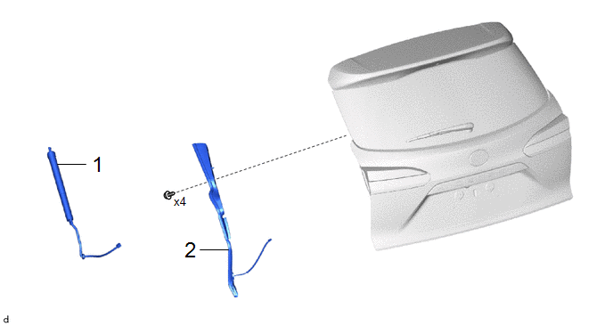
|
Procedure | Part Name Code |
.png) |
.png) |
 |
|---|---|---|---|---|---|
|
1 | POWER BACK DOOR UNIT ASSEMBLY SET |
68920 | - |
- | - |
|
2 | POWER BACK DOOR SENSOR ASSEMBLY |
84280D | - |
- | - |
CAUTION / NOTICE / HINT
HINT:
- Use the same procedure for the RH side and LH side.
- The following procedure is for the LH side.
PROCEDURE
1. REMOVE POWER BACK DOOR UNIT ASSEMBLY SET
Click here .gif)
2. REMOVE POWER BACK DOOR SENSOR ASSEMBLY

Inspection
INSPECTION
PROCEDURE
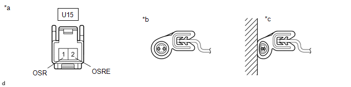
1. INSPECT POWER BACK DOOR SENSOR ASSEMBLY RH
|
*a | Component without harness connected (Power Back Door Sensor Assembly RH) |
*b | Not Pressed |
|
*c | Pressed |
- | - |
(a) Check the resistance of the power back door sensor Assembly RH.
(1) Measure the resistance according to the value(s) in the table below.
Standard Resistance:
|
Tester Connection | Condition |
Specified Condition |
|---|---|---|
|
U15-1 (OSR)- U15-2 (OSRE) |
Not pressed | 950 Ω to 1050 Ω |
|
U15-1 (OSR)- U15-2 (OSRE) |
Pressed | Below 100 Ω |
If the result is not as specified, replace the power back door sensor Assembly RH.
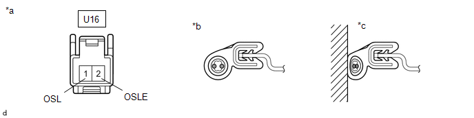
2. INSPECT POWER BACK DOOR SENSOR ASSEMBLY LH
|
*a | Component without harness connected (Power Back Door Sensor Assembly LH) |
*b | Not Pressed |
|
*c | Pressed |
- | - |
(a) Check the resistance of the power back door sensor Assembly LH.
(1) Measure the resistance according to the value(s) in the table below.
Standard Resistance:
|
Tester Connection | Condition |
Specified Condition |
|---|---|---|
|
U16-1 (OSL)- U16-2 (OSLE) |
Not pressed | 950 Ω to 1050 Ω |
|
U16-1 (OSL)- U16-2 (OSLE) |
Pressed | Below 100 Ω |
If the result is not as specified, replace the power back door sensor Assembly LH.
Installation
INSTALLATION
CAUTION / NOTICE / HINT
COMPONENTS (INSTALLATION)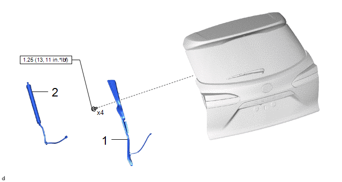
|
Procedure | Part Name Code |
.png) |
.png) |
 |
|---|---|---|---|---|---|
|
1 | POWER BACK DOOR SENSOR ASSEMBLY |
84280D | - |
- | - |
|
2 | POWER BACK DOOR UNIT ASSEMBLY SET |
68920 | - |
- | - |
.png) |
N*m (kgf*cm, ft.*lbf): Specified torque |
- | - |
CAUTION / NOTICE / HINT
HINT:
- Use the same procedure for the RH side and LH side.
- The following procedure is for the LH side.
PROCEDURE
1. INSTALL POWER BACK DOOR SENSOR ASSEMBLY
Torque:
1.25 N·m {13 kgf·cm, 11 in·lbf}
2. INSTALL POWER BACK DOOR UNIT ASSEMBLY SET
Click here .gif)

