Toyota Corolla Cross: Hydraulic Pressure Unit Component Internal Failure (P094296)
DESCRIPTION
Refer to DTC P02CB11.
Click here
.gif)
|
DTC No. | Detection Item |
DTC Detection Condition | Trouble Area |
MIL | Warning Indicate |
Note |
|---|---|---|---|---|---|---|
| P094296 |
Hydraulic Pressure Unit Component Internal Failure |
1. Diagnosis Condition 2. Malfunction Status 3. Malfunction Time 4. Other
|
| Comes on (For Mexico Models: Does not come on) |
Does not come on (For Mexico Models: Blinks) |
SAE Code: P0942 |
MONITOR STRATEGY
|
Related DTCs | P0942: Electric transmission fluid pump (starter / generator control module) performance |
|
Required Sensors/Components (Main) | Engine stop and start ECU |
|
Required Sensors/Components (Related) | - |
|
Frequency of Operation | Continuous |
|
Duration | 0.15 seconds |
| MIL Operation |
2 driving cycles |
| Sequence of Operation |
None |
TYPICAL ENABLING CONDITIONS
|
All of the following conditions are met |
- |
| Battery voltage |
8 V or higher |
|
Time after battery voltage 8 V or higher |
0.5 seconds or more |
|
Write inhibit | permit |
|
Time after write status forbiddance to permit |
0.5 seconds or more |
|
Ignition switch | ON |
|
Time after ignition switch is off to ON |
0.5 seconds or more |
|
Starter | Off |
|
Time after starter on to off |
0.5 seconds or more |
|
Time after ignition switch is off to ON |
3 seconds or more |
TYPICAL MALFUNCTION THRESHOLDS
|
Electric transmission fluid pump functional fail detected by TCM |
detected |
CONFIRMATION DRIVING PATTERN
CONFIRMATION AFTER TROUBLESHOOTING
HINT:
- If the cable is disconnected from the auxiliary battery terminal, stop and start control is prohibited until refresh charge is completed.
In this case, let the vehicle idle to complete the refresh charge. The refresh charge is complete when the Data List item Status of Battery Charge Control changes from "Refresh Charge Mode". (Usually, by idling the engine for 5 to 60 minutes with the auxiliary battery fluid temperature at 11°C (52°F) or higher, the refresh charge will be completed.)
- If the GTS is not available and the Data List item Status of Battery Charge Control cannot be checked, charge the auxiliary battery by idling the engine for approximately 5 to 60 minutes or driving the vehicle, and then drive the vehicle and check that stop and start control operates.
If the engine is started with the hood open, the system determines that a jump start has occurred. Therefore, make sure that the hood is closed before starting the engine and driving the vehicle.
- After the refresh charge completes, turn the ignition switch off, wait for at least 30 seconds, and then start the engine again. If the vehicle enters refresh charge mode again while the engine is idling, the initial refresh charge did not properly complete, so wait for the refresh charge to complete.
- Allow the engine to idle for 3 minutes after it is warmed up and check that the engine idle speed is within 50 rpm of the target idle speed.
(a) Clear the DTCs.
Powertrain > Stop and Start > Clear DTCs(b) Start the engine and warm it up.
(c) Drive the vehicle at 7 km/h (4 mph) or more.
CAUTION:
When performing Confirmation Driving Pattern, obey all speed limits and traffic laws.
(d) Depress the brake pedal and stop the vehicle.
(e) Keep the engine stopped by stop and start control. (Keep the shift lever in D.)
(f) Release the brake pedal with the shift lever in D to start the engine.
(g) Check that no DTCs are output.
Powertrain > Stop and Start > Trouble CodesSTOP AND START SYSTEM OPERATION CHECK
Click here
WIRING DIAGRAM
Refer to DTC P0C2B11.
Click here
CAUTION / NOTICE / HINT
NOTICE:
- Before replacing the engine stop and start ECU, read the number of starter operations and write it into a new engine stop and start ECU.
Click here
- After replacing the engine stop and start ECU, perform learning of the external backup boost converter (eco run vehicle converter assembly).
Click here
- After replacing the engine stop and start ECU or air conditioning amplifier assembly, reset and perform learning of the air conditioning information in the engine stop and start ECU.
Click here
- When the ECM is replaced on a vehicle with a non-specified auxiliary battery, it is necessary to perform auxiliary battery type switching.
Click here
- When the engine stop and start ECU or oil pump with motor assembly is replaced, check the oil pump with motor assembly.
Click here
HINT:
- Using the GTS, read the freeze frame data before troubleshooting. System condition information is recorded as freeze frame data the moment a DTC is stored. This information can be useful when troubleshooting.
Click here
- For wire harness and connector inspection procedures and precautions, refer to
- DTCs for the stop and start system are not cleared even if the malfunction has been repaired. After repairing the malfunction, be sure to clear the DTCs.
PROCEDURE
|
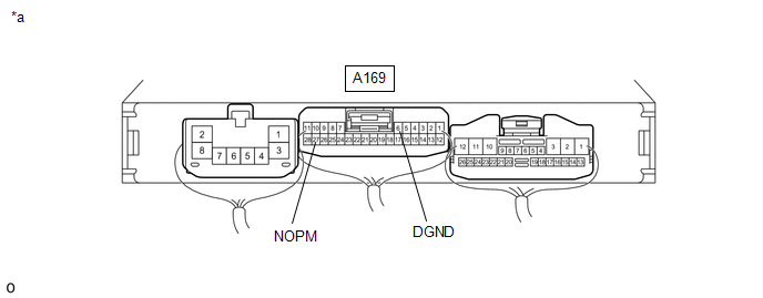
1. | CHECK ENGINE STOP AND START ECU (NOPM AND DGND TERMINAL WAVEFORM) |
(a) Drive the vehicle to warm up the engine and CVT fluid.
HINT:
The oil pump with motor assembly may not operate properly if the CVT fluid temperature is low. Make sure to warm up the CVT fluid before performing the Active Test. (CVT fluid temperature: 25°C (77°F) or higher)
(b) Turn the ignition switch to ON.
HINT:
Do not start the engine.
(c) Connect an oscilloscope to the NOPM and DGND terminals of the engine stop and start ECU connector.
|
*a | Component with harness connected (Engine Stop and Start ECU) |
- | - |
(d) Enter the following menus.
Powertrain > Stop and Start > Active Test|
Tester Display |
|---|
| Oil Pump |
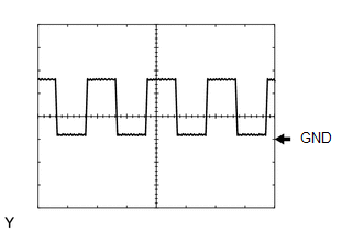
| (e) Check the waveform while performing the Active Test.
Standard: The waveform is similar to that shown in the illustration with no noise. Result:
HINT:
|
|
| B |
.gif) | REPLACE OIL PUMP (CONTINUOUSLY VARIABLE TRANSAXLE ASSEMBLY)
|
|
.gif)
| 2. |
CLEAR DTC |
(a) Clear the DTCs.
Powertrain > Stop and Start > Clear DTCs
|
| 3. |
CHECK DTC OUTPUT |
(a) Start the engine.
(b) Perform a road test.
(c) Read the DTCs.
Powertrain > Stop and Start > Trouble Codes|
Result | Proceed to |
|---|---|
|
DTC P094296 is output |
A |
| DTC P094296 is not output |
B |
| A |
| REPLACE ENGINE STOP AND START ECU |
| B |
| USE SIMULATION METHOD TO CHECK |


