Toyota Corolla Cross: Hybrid/EV Battery Positive Contactor Circuit Short to Auxiliary Battery or Open (P0AD915)
DESCRIPTION
Refer to the description for DTC P0AD911.
Click here .gif)
|
DTC No. | Detection Item |
DTC Detection Condition |
Trouble Area | MIL |
Warning Indicate | Note |
|---|---|---|---|---|---|---|
|
P0AD915 | Hybrid/EV Battery Positive Contactor Circuit Short to Auxiliary Battery or Open |
Open or short to +B in the SMRB circuit: Primary circuit of SMR (+) is malfunctioning. (2 trip detection logic) |
| Does not come on |
Master Warning: Comes on |
SAE Code: P0ADC |
CONFIRMATION DRIVING PATTERN
HINT:
After repair has been completed, clear the DTC and then check that the vehicle has returned to normal by performing the following All Readiness check procedure.
Click here
- Connect the GTS to the DLC3.
- Turn the ignition switch to ON and turn the GTS on.
- Clear the DTCs (even if no DTCs are stored, perform the clear DTC procedure).
- Turn the ignition switch off and wait for 2 minutes or more.
- Turn the ignition switch to ON (READY) and wait for 30 seconds or more.
- Turn the ignition switch off and wait for 2 minutes or more.
- Turn the ignition switch to ON and turn the GTS on.
- Enter the following menus: Powertrain / Hybrid Control / Utility / All Readiness.
- Check the DTC judgment result.
HINT:
- If the judgment result shows NORMAL, the system is normal.
- If the judgment result shows ABNORMAL, the system has a malfunction.
- If the judgment result shows INCOMPLETE, perform driving pattern again.
WIRING DIAGRAM
Refer to the wiring diagram for the HV Battery High-voltage Line Circuit.
Click here
CAUTION / NOTICE / HINT
CAUTION:
Refer to the precautions before inspecting high voltage circuit.
Click here
NOTICE:
- After the ignition switch is turned off, there may be a waiting time before disconnecting the negative (-) auxiliary battery terminal.
Click here
- When disconnecting and reconnecting the auxiliary battery
HINT:
When disconnecting and reconnecting the auxiliary battery, there is an automatic learning function that completes learning when the respective system is used.
Click here
HINT:
If DTC P0AD915 is output, the ignition switch cannot be turned to ON (READY).
PROCEDURE
|
1. | READ VALUE USING GTS (SMRB STATUS) |
(a) Read the Data List.
Powertrain > Hybrid Control > Data List|
Tester Display |
|---|
|
SMRB Status |
Standard:
|
Tester Display | Condition |
Specified Condition |
|---|---|---|
|
SMRB Status | Ignition switch ON |
OFF |
(b) Turn the ignition switch off.
| NG | .gif) | GO TO STEP 5 |
|
.gif)
|
2. | CHECK CONNECTOR CONNECTION CONDITION (HYBRID VEHICLE CONTROL ECU CONNECTOR) |
Click here
| NG | | CONNECT SECURELY |
|
|
3. | CHECK CONNECTOR CONNECTION CONDITION (FLOOR WIRE CONNECTOR) |
Click here
|
Result | Proceed to |
|---|---|
|
OK | A |
|
NG (The connector is not connected securely.) |
B |
| NG (The terminals are not making secure contact or are deformed, or water or foreign matter exists in the connector.) |
C |
| B | | CONNECT SECURELY |
| C | | REPAIR OR REPLACE HARNESS OR CONNECTOR |
|
|
4. | CHECK CONNECTOR CONNECTION CONDITION (HV BATTERY JUNCTION BLOCK ASSEMBLY CONNECTOR) |
Click here
| OK | | CHECK FOR INTERMITTENT PROBLEMS |
| NG | | CONNECT SECURELY |
|
5. | CHECK HARNESS AND CONNECTOR (SMRB VOLTAGE) |
(a) Turn the ignition switch to ON.
(b) Measure the voltage according to the value(s) in the table below.
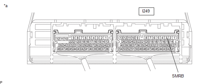
|
*a | Component with harness connected (Hybrid Vehicle Control ECU) |
- | - |
Standard Voltage:
|
Tester Connection | Condition |
Specified Condition |
|---|---|---|
|
I249-3 (SMRB) - Body ground |
Ignition switch ON |
Below 1 V |
(c) Turn the ignition switch off.
| NG | | GO TO STEP 7 |
|
|
6. | CHECK CONNECTOR CONNECTION CONDITION (HYBRID VEHICLE CONTROL ECU CONNECTOR) |
Click here
| OK | | REPLACE HYBRID VEHICLE CONTROL ECU |
| NG | | CONNECT SECURELY |
|
7. | CHECK HARNESS AND CONNECTOR (HYBRID VEHICLE CONTROL ECU - BODY GROUND) |
(a) Disconnect the hybrid vehicle control ECU connector.
(b) Measure the resistance according to the value(s) in the table below.
Standard Resistance:
|
Tester Connection | Condition |
Specified Condition |
|---|---|---|
|
I249-3 (SMRB) - Body ground |
Ignition switch off |
20.6 to 40.8 Ω |
(c) Reconnect the hybrid vehicle control ECU connector.
| NG | | GO TO STEP 9 |
|
|
8. | CHECK HARNESS AND CONNECTOR (SHORT TO POWER SUPPLY WIRES) |
CAUTION:
Be sure to wear insulated gloves.
(a) Check that the service plug grip is not installed.
NOTICE:
After removing the service plug grip, do not turn the ignition switch to ON (READY), unless instructed by the repair manual because this may cause a malfunction.
| (b) Disconnect the HV battery junction block assembly connector. |
|
.png)
(c) Disconnect the hybrid vehicle control ECU connector.
(d) Turn the ignition switch to ON.
(e) Measure the voltage according to the value(s) in the table below.
Standard Voltage:
|
Tester Connection | Condition |
Specified Condition |
|---|---|---|
|
I249-3 (SMRB) or O212-4 (SMRB) - Body ground |
Ignition switch ON |
Below 1 V |
NOTICE:
Turning the ignition switch to ON with the hybrid vehicle control ECU connector and the HV battery junction block assembly connector disconnected causes other DTCs to be stored. Clear the DTCs after performing this inspection.
(f) Turn the ignition switch off.
(g) Reconnect the hybrid vehicle control ECU connector.
(h) Reconnect the HV battery junction block assembly connector.
| OK | | REPLACE HYBRID VEHICLE CONTROL ECU |
| NG | | REPAIR OR REPLACE HARNESS OR CONNECTOR |
|
9. | CHECK CONNECTOR CONNECTION CONDITION (FLOOR WIRE CONNECTOR) |
Click here
|
Result | Proceed to |
|---|---|
|
OK | A |
|
NG (The connector is not connected securely.) |
B |
| NG (The terminals are not making secure contact or are deformed, or water or foreign matter exists in the connector.) |
C |
| B | | CONNECT SECURELY |
| C | | REPAIR OR REPLACE HARNESS OR CONNECTOR |
|
|
10. | CHECK HARNESS AND CONNECTOR (HYBRID VEHICLE CONTROL ECU - HV BATTERY JUNCTION BLOCK ASSEMBLY) |
CAUTION:
Be sure to wear insulated gloves.
(a) Check that the service plug grip is not installed.
NOTICE:
After removing the service plug grip, do not turn the ignition switch to ON (READY), unless instructed by the repair manual because this may cause a malfunction.
| (b) Disconnect the HV battery junction block assembly connector. |
|
(c) Disconnect the hybrid vehicle control ECU connector.
(d) Measure the resistance according to the value(s) in the table below.
Standard Resistance (Check for Open):
|
Tester Connection | Condition |
Specified Condition |
|---|---|---|
|
I249-3 (SMRB) - O212-4 (SMRB) |
Ignition switch off |
Below 1 Ω |
Standard Resistance (Check for Short):
|
Tester Connection | Condition |
Specified Condition |
|---|---|---|
|
I249-3 (SMRB) or O212-4 (SMRB) - Body ground and other terminals |
Ignition switch off |
10 kΩ or higher |
(e) Reconnect the hybrid vehicle control ECU connector.
(f) Reconnect the HV battery junction block assembly connector.
| NG | | REPAIR OR REPLACE HARNESS OR CONNECTOR |
|
|
11. | CHECK HARNESS AND CONNECTOR (HV BATTERY JUNCTION BLOCK ASSEMBLY - BODY GROUND) |
CAUTION:
Be sure to wear insulated gloves.
(a) Check that the service plug grip is not installed.
NOTICE:
After removing the service plug grip, do not turn the ignition switch to ON (READY), unless instructed by the repair manual because this may cause a malfunction.
(b) Disconnect the HV battery junction block assembly connector.
(c) Measure the resistance according to the value(s) in the table below.
Standard Resistance:
|
Tester Connection | Condition |
Specified Condition |
|---|---|---|
|
O212-2 (GND) - Body ground |
Ignition switch off |
Below 1 Ω |
(d) Reconnect the HV battery junction block assembly connector.
| NG | | REPAIR OR REPLACE HARNESS OR CONNECTOR |
|
|
12. | INSPECT HV BATTERY JUNCTION BLOCK ASSEMBLY (SMRB) |
CAUTION:
Be sure to wear insulated gloves.
(a) Check that the service plug grip is not installed.
NOTICE:
After removing the service plug grip, do not turn the ignition switch to ON (READY), unless instructed by the repair manual because this may cause a malfunction.
(b) Disconnect the HV battery junction block assembly connector.
(c) Measure the resistance according to the value(s) in the table below.
.png)
|
*a | Component without harness connected (HV Battery Junction Block Assembly) |
- | - |
Standard Resistance:
|
Tester Connection | Condition |
Specified Condition |
|---|---|---|
|
O212-4 (SMRB) - O212-2 (GND) |
-40 to 80°C (-40 to 176°F) |
20.6 to 40.8 Ω |
(d) Reconnect the HV battery junction block assembly connector.
| OK | | CHECK FOR INTERMITTENT PROBLEMS |
| NG | | REPLACE HV BATTERY JUNCTION BLOCK ASSEMBLY |
READ NEXT:
 Hybrid/EV Battery Negative Contactor Circuit Short to Ground (P0ADD11)
DESCRIPTION Refer to the description for DTC P0AD911.
Click here
DTC No. Detection Item
DTC Detection Condition
Trouble Area MIL
Warning Indicate Note
P0AD
Hybrid/EV Battery Negative Contactor Circuit Short to Auxiliary Battery or Open (P0ADD15)
DESCRIPTION Refer to the description for DTC P0AD911.
Click here
DTC No. Detection Item
DTC Detection Condition
Trouble Area MIL
Warning Indicate Note
P0AD
Hybrid/EV Battery "A" Voltage Sensor Voltage Out of Range (P0B231C)
DTC SUMMARY MALFUNCTION DESCRIPTION The hybrid vehicle control ECU detects a VB sensor malfunction.
The cause of this malfunction may be one of the following: Battery ECU assembly VB sensor interna
SEE MORE:
 Vehicle Speed Signal Circuit Open (B228231,B228262)
DESCRIPTION DTC B228231 is stored when the vehicle speed signal sent by the skid control ECU via direct line and the vehicle speed signal sent via CAN communication do not match.
DTC B228262 is stored when a malfunction in the vehicle speed sensor is detected.
DTC No. Detection Item
D
VEHICLE CONTROL HISTORY (RoB)
VEHICLE CONTROL HISTORY (RoB)
DESCRIPTION
Vehicle Control History (RoB) is a function that captures and stores
ECU data when triggered by specific vehicle behavior.
If the customer states that the engine stalled or will not start, it
may be possible to diagnose the cause of the malfu
