Toyota Corolla Cross: Hybrid/EV Battery Cooling Fan 1 Component Internal Failure (P0A8196,P0A8198)
DESCRIPTION
Refer to the description for DTC P0A8111.
Click here .gif)
|
DTC No. | Detection Item |
DTC Detection Condition |
Trouble Area | MIL |
Warning Indicate | Note |
|---|---|---|---|---|---|---|
|
P0A8196 | Hybrid/EV Battery Cooling Fan 1 Component Internal Failure |
The battery cooling blower assembly is malfunctioning and the actual speed is not within the specified range of the target speed calculated by the ECU.* *: This DTC is not stored when "Hybrid/EV Battery Cooling Fan 1 Frequency" is excessively low or high. (2 trip detection logic) |
| Comes on |
Master Warning: Comes on |
SAE Code: P0A82 |
|
P0A8198 | Hybrid/EV Battery Cooling Fan 1 Component or System Over Temperature |
The HV battery temperature is high and the battery cooling blower assembly is malfunctioning and the actual speed is not within the specified range of the target speed calculated by the ECU.* *: This DTC is not stored when "Hybrid/EV Battery Cooling Fan 1 Frequency" is excessively low or high. (1 trip detection logic) |
| Comes on |
Master Warning: Comes on |
SAE Code: P0A82 |
HINT:
"Hybrid/EV Battery Cooling Fan 1 Frequency" is detected when the battery cooling blower assembly is operating and its value changes in proportion to the battery cooling blower assembly rotation speed.
MONITOR DESCRIPTION
If the battery ECU assembly detects that the speed of the battery cooling blower assembly is outside the normal operating range, it will illuminate the MIL and store a DTC.
MONITOR STRATEGY
|
Related DTCs | P0A82 (INF P0A8196): Hybrid/EV Battery Cooling Fan 1 Component Internal Failure P0A82 (INF P0A8198): Hybrid/EV Battery Cooling Fan 1 Component or System Over Temperature |
|
Required sensors/components | Battery cooling blower assembly |
|
Frequency of operation | Continuous |
|
Duration | TMC's intellectual property |
|
MIL operation | 1 driving cycle / 2 driving cycles |
|
Sequence of operation | None |
TYPICAL ENABLING CONDITIONS
|
The monitor will run whenever the following DTCs are not stored |
TMC's intellectual property |
|
Other conditions belong to TMC's intellectual property |
- |
TYPICAL MALFUNCTION THRESHOLDS
|
TMC's intellectual property | - |
COMPONENT OPERATING RANGE
|
Battery ECU assembly | DTC P0A82 (INF P0A8196) is not detected DTC P0A82 (INF P0A8198) is not detected |
CONFIRMATION DRIVING PATTERN
HINT:
- After repair has been completed, clear the DTC and then check that the vehicle has returned to normal by performing the following All Readiness check procedure.
Click here
- When clearing the permanent DTCs, refer to the "CLEAR PERMANENT DTC" procedure.
Click here
- Connect the GTS to the DLC3.
- Turn the ignition switch to ON and turn the GTS on.
- Clear the DTCs (even if no DTCs are stored, perform the clear DTC procedure).
- Turn the ignition switch off and wait for 2 minutes or more.
- Turn the ignition switch to ON (READY) and turn the GTS on.
- Enter the following menus: Powertrain / HV Battery / Active Test / Control the Hybrid/EV Battery Cooling Fan.[*1]
- Operate the battery cooling blower assembly in each fan mode, 1 through 6, for 60 seconds or more.[*2]
HINT:
- Operation of the battery cooling blower assembly can be confirmed by checking if air is sucked into the air intake port of the intake duct.
- [*1] to [*2]: Normal judgment procedure.
The normal judgment procedure is used to complete DTC judgment and also used when clearing permanent DTCs.
- Enter the following menus: Powertrain / HV Battery / Utility / All Readiness.
- Check the DTC judgment result.
HINT:
- If the judgment result shows NORMAL, the system is normal.
- If the judgment result shows ABNORMAL, the system has a malfunction.
- If the judgment result shows INCOMPLETE, perform the normal judgment procedure again.
WIRING DIAGRAM
Refer to the wiring diagram for DTC P0A8111.
Click here
CAUTION / NOTICE / HINT
CAUTION:
Refer to the precautions before inspecting high voltage circuit.
Click here
NOTICE:
- After the ignition switch is turned off, there may be a waiting time before disconnecting the negative (-) auxiliary battery terminal.
Click here
- When disconnecting and reconnecting the auxiliary battery
HINT:
When disconnecting and reconnecting the auxiliary battery, there is an automatic learning function that completes learning when the respective system is used.
Click here
PROCEDURE
|
1. | CHECK DTC OUTPUT (HV BATTERY, HYBRID CONTROL) |
(a) Check for DTCs.
Powertrain > HV Battery > Trouble Codes Powertrain > Hybrid Control > Trouble Codes|
Result | Proceed to |
|---|---|
|
P0A8196 or P0A8198 only is output, or DTCs except the ones in the table below are also output. |
A |
| DTCs of hybrid battery system in the table below are output. |
B |
| DTCs of hybrid control system in the table below are output. |
C |
|
System | Relevant DTC | |
|---|---|---|
|
Hybrid battery system |
P060A47 | Hybrid/EV Battery Energy Control Module Monitoring Processor Watchdog / Safety MCU Failure |
|
P060B49 | Hybrid/EV Battery Energy Control Module A/D Processing Internal Electronic Failure | |
|
P060687 | Hybrid/EV Battery Energy Control Module Processor to Monitoring Processor Missing Message | |
|
Hybrid control system |
P0A1F94 | Hybrid/EV Battery Energy Control Module Unexpected Operation |
(b) Turn the ignition switch off.
| B | .gif) | GO TO DTC CHART (HYBRID BATTERY SYSTEM) |
| C | | GO TO DTC CHART (HYBRID CONTROL SYSTEM) |
|
.gif)
|
2. | CHECK DUCT AND BLOWER |
CAUTION:
Be sure to wear insulated gloves.
(a) Check that the service plug grip is not installed.
NOTICE:
After removing the service plug grip, do not turn the ignition switch to ON (READY), unless instructed by the repair manual because this may cause a malfunction.
| (b) Check that the No. 1 HV battery intake filter, No. 1 hybrid battery intake duct and battery cooling blower assembly blower are not disconnected, damaged, or clogged with foreign matter. OK: The No. 1 HV battery intake filter, No. 1 hybrid battery intake duct and battery cooling blower assembly blower are not disconnected, damaged, or clogged with foreign matter. |
|

| NG | | CORRECT THE PROBLEM |
|
|
3. | CHECK HARNESS AND CONNECTOR (BATTERY ECU ASSEMBLY - BATTERY COOLING BLOWER ASSEMBLY) |
Click here
| NG | | REPAIR OR REPLACE HARNESS OR CONNECTOR |
|
|
4. | CHECK HARNESS AND CONNECTOR (BATTERY ECU ASSEMBLY - BATTERY COOLING BLOWER ASSEMBLY) |
Click here
| NG | | REPAIR OR REPLACE HARNESS OR CONNECTOR |
|
|
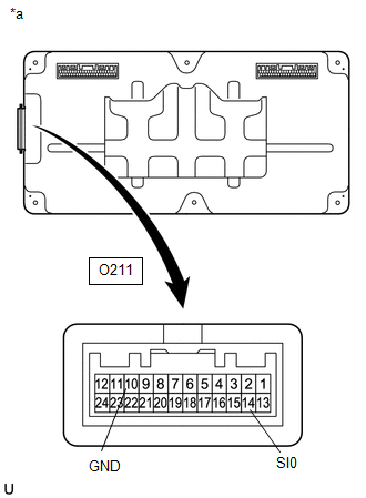
5. | CHECK BATTERY ECU ASSEMBLY (GROUND SHORT CHECK) |
(a) Remove the battery ECU assembly.
Click here
| (b) Measure the resistance according to the value(s) in the table below. Standard Resistance:
|
|
(c) Install the battery ECU assembly.
| NG | | REPLACE BATTERY ECU ASSEMBLY |
|
|
6. | READ VALUE USING GTS (HYBRID/EV BATTERY COOLING FAN 1 FREQUENCY) |
Click here
|
Result | Proceed to |
|---|---|
|
Both of the value in the Data List (Hybrid/EV Battery Cooling Fan 1 Frequency) and the actual measured value at the battery ECU assembly connector are 0 Hz. |
A |
| Other than above |
B |
| B | | GO TO STEP 8 |
|
|
7. | CHECK BATTERY ECU ASSEMBLY |
Click here
| OK | | REPLACE BATTERY COOLING BLOWER ASSEMBLY |
| NG | | REPLACE BATTERY ECU ASSEMBLY |
|
8. | CHECK BATTERY ECU ASSEMBLY (FREQUENCY) |
Click here
| OK | | REPLACE BATTERY COOLING BLOWER ASSEMBLY |
| NG | | REPLACE BATTERY ECU ASSEMBLY |


