Toyota Corolla Cross: Hybrid/EV Battery Temperature Sensor "A" Circuit Short to Ground (P0A9B11,...,P0C3315)
DESCRIPTION
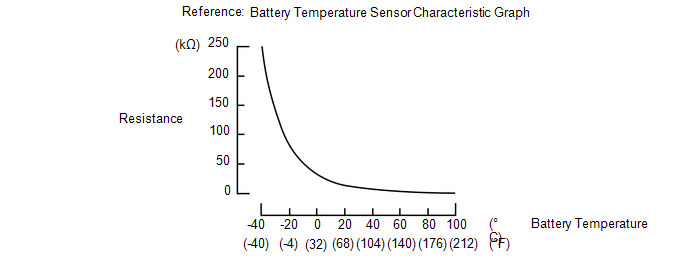
The battery temperature sensors are provided at 6 locations of the HV battery. The resistance of the thermistor, which is built into each battery temperature sensor, varies in accordance with changes in the HV battery temperature. The lower the battery temperature, the higher the thermistor resistance. Conversely, the higher the temperature, the lower the resistance. The battery ECU assembly uses the battery temperature sensors to detect the HV battery temperature. Based on the results of this detection, the battery ECU assembly controls the blower fan. (The blower fan starts when the HV battery temperature rises above a predetermined level.)
Temperature Sensor Identification Cross Reference Table:
|
DTC Title Sensor | Battery Temperature Sensor |
GTS Display |
|---|---|---|
|
A | 0 |
1 |
| B |
1 | 2 |
|
C | 2 |
3 |
| D |
3 | 4 |
|
E | 4 |
5 |
| F |
5 | 6 |
HINT:
Use the reference table above to determine which battery temperature sensor corresponds to each DTC. For example, sensor A in the DTC title column is battery temperature sensor 0. This sensor is displayed as Hybrid/EV Battery Temperature 1 in the Data List.
|
DTC No. | Detection Item |
DTC Detection Condition |
Trouble Area | MIL |
Warning Indicate | Note |
|---|---|---|---|---|---|---|
|
P0A9B11 | Hybrid/EV Battery Temperature Sensor "A" Circuit Short to Ground |
The battery temperature sensor is malfunctioning, its output voltage is lower than the specified value (short circuit) and the detected temperature is higher than the specified value. (1 trip detection logic) |
| Comes on |
Master warning: Comes on |
SAE Code: P0A9D |
|
P0A9B15 | Hybrid/EV Battery Temperature Sensor "A" Circuit Short to Auxiliary Battery or Open |
The battery temperature sensor is malfunctioning, its output voltage is higher than the specified value (short to +B or open) and the detected temperature is lower than the specified value. (1 trip detection logic) |
| Comes on |
Master warning: Comes on |
SAE Code: P0A9E |
|
P0AC511 | Hybrid/EV Battery Temperature Sensor "B" Circuit Short to Ground |
The battery temperature sensor is malfunctioning, its output voltage is lower than the specified value (short circuit) and the detected temperature is higher than the specified value. (1 trip detection logic) |
| Comes on |
Master warning: Comes on |
SAE Code: P0AC7 |
|
P0AC515 | Hybrid/EV Battery Temperature Sensor "B" Circuit Short to Auxiliary Battery or Open |
The battery temperature sensor is malfunctioning, its output voltage is higher than the specified value (short to +B or open) and the detected temperature is lower than the specified value. (1 trip detection logic) |
| Comes on |
Master warning: Comes on |
SAE Code: P0AC8 |
|
P0ACA11 | Hybrid/EV Battery Temperature Sensor "C" Circuit Short to Ground |
The battery temperature sensor is malfunctioning, its output voltage is lower than the specified value (short circuit) and the detected temperature is higher than the specified value. (1 trip detection logic) |
| Comes on |
Master warning: Comes on |
SAE Code: P0ACC |
|
P0ACA15 | Hybrid/EV Battery Temperature Sensor "C" Circuit Short to Auxiliary Battery or Open |
The battery temperature sensor is malfunctioning, its output voltage is higher than the specified value (short to +B or open) and the detected temperature is lower than the specified value. (1 trip detection logic) |
| Comes on |
Master warning: Comes on |
SAE Code: P0ACD |
|
P0AE811 | Hybrid/EV Battery Temperature Sensor "D" Circuit Short to Ground |
The battery temperature sensor is malfunctioning, its output voltage is lower than the specified value (short circuit) and the detected temperature is higher than the specified value. (1 trip detection logic) |
| Comes on |
Master warning: Comes on |
SAE Code: P0AEA |
|
P0AE815 | Hybrid/EV Battery Temperature Sensor "D" Circuit Short to Auxiliary Battery or Open |
The battery temperature sensor is malfunctioning, its output voltage is higher than the specified value (short to +B or open) and the detected temperature is lower than the specified value. (1 trip detection logic) |
| Comes on |
Master warning: Comes on |
SAE Code: P0AEB |
|
P0BC211 | Hybrid/EV Battery Temperature Sensor "E" Circuit Short to Ground |
The battery temperature sensor is malfunctioning, its output voltage is lower than the specified value (short circuit) and the detected temperature is higher than the specified value. (1 trip detection logic) |
| Comes on |
Master warning: Comes on |
SAE Code: P0BC4 |
|
P0BC215 | Hybrid/EV Battery Temperature Sensor "E" Circuit Short to Auxiliary Battery or Open |
The battery temperature sensor is malfunctioning, its output voltage is higher than the specified value (short to +B or open) and the detected temperature is lower than the specified value. (1 trip detection logic) |
| Comes on |
Master warning: Comes on |
SAE Code: P0BC5 |
|
P0C3311 | Hybrid/EV Battery Temperature Sensor "F" Circuit Short to Ground |
The battery temperature sensor is malfunctioning, its output voltage is lower than the specified value (short circuit) and the detected temperature is higher than the specified value. (1 trip detection logic) |
| Comes on |
Master warning: Comes on |
SAE Code: P0C35 |
|
P0C3315 | Hybrid/EV Battery Temperature Sensor "F" Circuit Short to Auxiliary Battery or Open |
The battery temperature sensor is malfunctioning, its output voltage is higher than the specified value (short to +B or open) and the detected temperature is lower than the specified value. (1 trip detection logic) |
| Comes on |
Master warning: Comes on |
SAE Code: P0C36 |
HINT:
- After checking for the above DTCs, check the hybrid system Data List item "Hybrid/EV Battery Temperature" using the GTS.
Temperature Displayed
Malfunction
Below -45°C (-49°F)
Open or +B short circuit
95°C (203°F) or more
GND short circuit
- If the vehicle as is left as is for 24 hours, the value of "Hybrid/EV Battery Temperature" will be almost the same as the ambient temperature.
MONITOR DESCRIPTION
If the battery ECU assembly detects a malfunction in a HV battery temperature sensor, the battery ECU will illuminate the MIL and store a DTC.
MONITOR STRATEGY
|
Related DTCs | P0A9D (INF P0A9B11), P0AC7 (INF P0AC511), P0ACC (INF P0ACA11), P0AEA (INF P0AE811), P0BC4 (INF P0BC211), P0C35 (INF P0C3311): Battery temperature sensor circuit malfunction (GND short) P0A9E (INF P0A9B15), P0AC8 (INF P0AC515), P0ACD (INF P0ACA15), P0AEB (INF P0AE815), P0BC5 (INF P0BC215), P0C36 (INF P0C3315): Battery temperature sensor circuit malfunction (open) |
|
Required sensors/components | Battery temperature sensor |
|
Frequency of operation | Continuous |
|
Duration | TMC's intellectual property |
|
MIL operation | Immediately |
|
Sequence of operation | None |
TYPICAL ENABLING CONDITIONS
|
The monitor will run whenever the following DTCs are not stored |
TMC's intellectual property |
|
Other conditions belong to TMC's intellectual property |
- |
TYPICAL MALFUNCTION THRESHOLDS
|
TMC's intellectual property | - |
COMPONENT OPERATING RANGE
|
Battery ECU assembly | DTC P0A9D (INF P0A9B11) is not detected DTC P0AC7 (INF P0AC511) is not detected DTC P0ACC (INF P0ACA11) is not detected DTC P0BC4 (INF P0BC211) is not detected DTC P0C35 (INF P0C3311) is not detected DTC P0A9E (INF P0A9B15) is not detected DTC P0AC8 (INF P0AC515) is not detected DTC P0ACD (INF P0ACA15) is not detected DTC P0AEB (INF P0AE815) is not detected DTC P0BC5 (INF P0BC215) is not detected DTC P0C36 (INF P0C3315) is not detected |
CONFIRMATION DRIVING PATTERN
HINT:
- After repair has been completed, clear the DTC and then check that the vehicle has returned to normal by performing the following All Readiness check procedure.
Click here
.gif)
- When clearing the permanent DTCs, refer to the "CLEAR PERMANENT DTC" procedure.
Click here
- Connect the GTS to the DLC3.
- Turn the ignition switch to ON and turn the GTS on.
- Clear the DTCs (even if no DTCs are stored, perform the clear DTC procedure).
- Turn the ignition switch off and wait for 2 minutes or more.
- Turn the ignition switch to ON and turn the GTS on.
- With ignition switch ON and wait for 10 seconds or more.[*1]
HINT:
[*1]: Normal judgment procedure.
The normal judgment procedure is used to complete DTC judgment and also used when clearing permanent DTCs.
- Enter the following menus: Powertrain / HV Battery / Utility / All Readiness.
- Check the DTC judgment result.
HINT:
- If the judgment result shows NORMAL, the system is normal.
- If the judgment result shows ABNORMAL, the system has a malfunction.
- If the judgment result shows INCOMPLETE, perform the normal judgment procedure again.
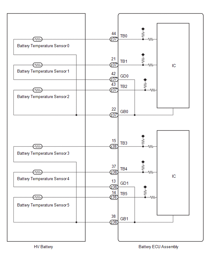
WIRING DIAGRAM
CAUTION / NOTICE / HINT
CAUTION:
Refer to the precautions before inspecting high voltage circuit.
Click here
NOTICE:
- After the ignition switch is turned off, there may be a waiting time before disconnecting the negative (-) auxiliary battery terminal.
Click here
- When disconnecting and reconnecting the auxiliary battery
HINT:
When disconnecting and reconnecting the auxiliary battery, there is an automatic learning function that completes learning when the respective system is used.
Click here
PROCEDURE
|
1. | CHECK DTC OUTPUT (HV BATTERY, HYBRID CONTROL) |
(a) Check for DTCs.
Powertrain > HV Battery > Trouble Codes Powertrain > Hybrid Control > Trouble Codes|
Result | Proceed to |
|---|---|
|
"P0A9B11, P0A9B15, P0AC511, P0AC515, P0ACA11, P0ACA15, P0AE811, P0AE815, P0BC211, P0BC215, P0C3311 or P0C3315" only is output, or DTCs except the ones in the table below are also output. |
A |
| DTCs of hybrid battery system in the table below are output. |
B |
| DTCs of hybrid control system in the table below are output. |
C |
|
System | Relevant DTC | |
|---|---|---|
|
Hybrid battery system |
P060A47 | Hybrid/EV Battery Energy Control Module Monitoring Processor Watchdog / Safety MCU Failure |
|
P060B49 | Hybrid/EV Battery Energy Control Module A/D Processing Internal Electronic Failure | |
|
P060687 | Hybrid/EV Battery Energy Control Module Processor to Monitoring Processor Missing Message | |
|
Hybrid control system |
P0A1F94 | Hybrid/EV Battery Energy Control Module Unexpected Operation |
(b) Turn the ignition switch off.
| B | .gif) | GO TO DTC CHART (HYBRID BATTERY SYSTEM) |
| C | | GO TO DTC CHART (HYBRID CONTROL SYSTEM) |
|
.gif)
|
2. | READ VALUE USING GTS (HYBRID/EV BATTERY TEMPERATURE) |
(a) Read the Data List.
Powertrain > HV Battery > Data List|
Tester Display |
|---|
|
Hybrid/EV Battery Temperature 1 |
|
Hybrid/EV Battery Temperature 2 |
|
Hybrid/EV Battery Temperature 3 |
|
Hybrid/EV Battery Temperature 4 |
|
Hybrid/EV Battery Temperature 5 |
|
Hybrid/EV Battery Temperature 6 |
HINT:
A malfunctioning sensor (battery temperature sensor 0, 1, 2, 3, or 5) can be determined by comparing the output temperature of the 6 battery temperature sensors.
(b) Turn the ignition switch off.
|
|
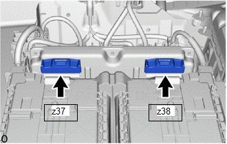
3. | CHECK CONNECTOR CONNECTION CONDITION (BATTERY ECU ASSEMBLY) |
CAUTION:
Be sure to wear insulated gloves and protective goggles.
(a) Check that the service plug grip is not installed.
NOTICE:
After removing the service plug grip, do not turn the ignition switch to ON (READY), unless instructed by the repair manual because this may cause a malfunction.
| (b) Check the connector connections and contact pressure of the relevant terminals for the battery ECU assembly. Click here OK: The connector is connected securely and there are no contact pressure problems. |
|
| NG | | CONNECT SECURELY |
|
|
4. | CHECK DTC |
(a) Check the DTCs that were output when the vehicle was brought to the workshop.
|
Result | Proceed to |
|---|---|
|
"P0A9B11, P0A9B15, P0AC511, P0AC515, P0ACA11 or P0ACA15" is also output. |
A |
| "P0AE811, P0AE815, P0BC211, P0BC215, P0C3311 or P0C3315" is also output. |
B |
| B | | GO TO STEP 6 |
|
|
5. | CHECK HV BATTERY (BATTERY TEMPERATURE SENSOR 0 to 2) |
CAUTION:
Be sure to wear insulated gloves and protective goggles.
(a) Check that the service plug grip is not installed.
NOTICE:
After removing the service plug grip, do not turn the ignition switch to ON (READY), unless instructed by the repair manual because this may cause a malfunction.
| (b) Disconnect the battery ECU assembly connector. NOTICE: Before disconnecting the connector, check that it is not loose or disconnected. |
|
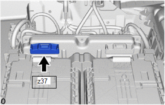
(c) Measure the resistance of the circuit for the malfunctioning sensor (battery temperature sensor 0 to 2).
Tester Connection:
|
Tester Connection | Battery Temperature Sensor |
|---|---|
|
z37-44 (TB0) - z37-22 (GB0) |
0 |
| z37-21 (TB1) - z37-42 (GD0) |
1 |
| z37-43 (TB2) - z37-22 (GB0) |
2 |
Standard Resistance:
|
Thermistor Temperature |
Condition | Specified Condition |
|---|---|---|
|
0 to 10°C (32 to 50°F) |
Ignition switch off |
17.68 to 27.83 kΩ |
|
10 to 20°C (50 to 68°F) |
Ignition switch off |
11.94 to 18.25 kΩ |
|
20 to 30°C (68 to 86°F) |
Ignition switch off |
8.21 to 12.24 kΩ |
|
30 to 40°C (86 to 104°F) |
Ignition switch off |
5.73 to 8.41 kΩ |
|
40 to 50°C (104 to 122°F) |
Ignition switch off |
4.08 to 5.91 kΩ |
(d) Measure the resistance according to the value (s) in the table below.
Standard Resistance:
|
Tester Connection | Condition |
Specified Condition |
|---|---|---|
|
z37-44 (TB0) - Body ground and other terminals (except z37-22 (GB0) and z37-43 (TB2)) |
Ignition switch off |
10 kΩ or higher |
|
z37-22 (GB0) - Body ground and other terminals (except z37-44 (TB0) and z37-43 (TB2)) |
Ignition switch off |
10 kΩ or higher |
|
z37-21 (TB1) - Body ground and other terminals (except z37-42 (GD0)) |
Ignition switch off |
10 kΩ or higher |
|
z37-42 (GD0) - Body ground and other terminals (except z37-21 (TB1)) |
Ignition switch off |
10 kΩ or higher |
|
z37-43 (TB2) - Body ground and other terminals (except z37-44 (TB0) and z37-22 (GB0)) |
Ignition switch off |
10 kΩ or higher |
(e) Reconnect the battery ECU assembly connector.
| OK | | REPLACE BATTERY ECU ASSEMBLY |
| NG | | REPLACE HV BATTERY |
|
6. | CHECK HV BATTERY (BATTERY TEMPERATURE SENSOR 3 to 5) |
CAUTION:
Be sure to wear insulated gloves and protective goggles.
(a) Check that the service plug grip is not installed.
NOTICE:
After removing the service plug grip, do not turn the ignition switch to ON (READY), unless instructed by the repair manual because this may cause a malfunction.
| (b) Disconnect the battery ECU assembly connector. NOTICE: Before disconnecting the connector, check that it is not loose or disconnected. |
|
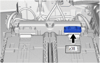
(c) Measure the resistance of the circuit for the malfunctioning sensor (battery temperature sensor 3 to 5).
Tester Connection:
|
Tester Connection | Battery Temperature Sensor |
|---|---|
|
z38-15 (TB3) - z38-38 (GB1) |
3 |
| z38-37 (TB4) - z38-13 (GD1) |
4 |
| z38-14 (TB5) - z38-38 (GB1) |
5 |
Standard Resistance:
|
Thermistor Temperature |
Condition | Specified Condition |
|---|---|---|
|
0 to 10°C (32 to 50°F) |
Ignition switch off |
17.68 to 27.83 kΩ |
|
10 to 20°C (50 to 68°F) |
Ignition switch off |
11.94 to 18.25 kΩ |
|
20 to 30°C (68 to 86°F) |
Ignition switch off |
8.21 to 12.24 kΩ |
|
30 to 40°C (86 to 104°F) |
Ignition switch off |
5.73 to 8.41 kΩ |
|
40 to 50°C (104 to 122°F) |
Ignition switch off |
4.08 to 5.91 kΩ |
(d) Measure the resistance according to the value (s) in the table below.
Standard Resistance:
|
Tester Connection | Condition |
Specified Condition |
|---|---|---|
|
z38-15 (TB3) - Body ground and other terminals (except z38-38 (GB1) and z38-14 (TB5)) |
Ignition switch off |
10 kΩ or higher |
|
z38-38 (GB1) - Body ground and other terminals (except z38-15 (TB3) and z38-14 (TB5)) |
Ignition switch off |
10 kΩ or higher |
|
z38-37 (TB4) - Body ground and other terminals (except z38-13 (GD1)) |
Ignition switch off |
10 kΩ or higher |
|
z38-13 (GD1) - Body ground and other terminals (except z38-37 (TB4)) |
Ignition switch off |
10 kΩ or higher |
|
z38-14 (TB5) - Body ground and other terminals (except z38-15 (TB3) and z38-38 (GB1)) |
Ignition switch off |
10 kΩ or higher |
(e) Reconnect the battery ECU assembly connector.
| OK | | REPLACE BATTERY ECU ASSEMBLY |
| NG | | REPLACE HV BATTERY |
READ NEXT:
 Hybrid/EV Battery Temperature Sensor "A" Voltage Out of Range (P0A9B1C,P0AC51C,P0ACA1C,P0AE81C,P0BC21C,P0C331C)
DESCRIPTION Refer to the description for DTC P0A9B11.
Click here
DTC No. Detection Item
DTC Detection Condition
Trouble Area MIL
Warning Indicate Note
P0A9
Hybrid/EV Battery Temperature Sensor "A" Signal Stuck In Range (P0A9B2A,P0AC52A,P0ACA2A,P0AE82A,P0BC22A,P0C332A,P306562,P306A62)
DESCRIPTION Refer to the description for DTC P0A9B11.
Click here
DTC No. Detection Item
DTC Detection Condition
Trouble Area MIL
Warning Indicate Note
P0A9
Hybrid/EV Battery Air Temperature Sensor "A" Circuit Short to Ground (P0AAC11,P0AAC15)
DESCRIPTION The inlet air temperature sensor (HV battery) is mounted on the HV battery. The resistance of the sensor varies in accordance with changes in the intake air temperature. The characteristic
SEE MORE:
 Utility
UTILITY ALL READINESS
HINT:
With "All Readiness", you can check whether or not the DTC judgment has been completed by using the GTS.
Check "All Readiness" after simulating malfunction symptoms or for validation after finishing repairs.
(a) Clear the DTCs (even if no DTCs are s
Lubrication System
On-vehicle InspectionON-VEHICLE INSPECTION PROCEDURE
1. CHECK ENGINE OIL LEVEL (a) Warm up and stop the engine, then wait for 5 minutes.
(b) Check that the engine oil level is between the low level and full level marks on the engine oil level dipstick.
If the level is low, check for engine oil
