Toyota Corolla Cross: Battery Cooling Filter
Removal
REMOVAL
CAUTION / NOTICE / HINT
COMPONENTS (REMOVAL)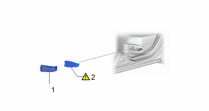
|
Procedure |
Part Name Code |
.png) |
.png) |
.png) |
|
|---|---|---|---|---|---|
|
1 |
BATTERY SERVICE HOLE COVER |
- |
- |
- |
- |
|
2 |
NO. 1 HV BATTERY INTAKE FILTER |
G92DH |
|
- |
- |
.gif)
|
*A |
for NICKEL METAL HYDRIDE BATTERY |
*B |
for LITHIUM-ION BATTERY |
PROCEDURE
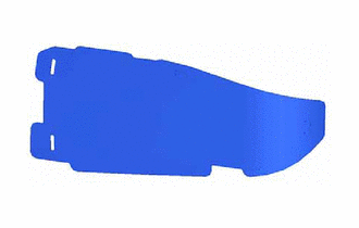
1. REMOVE BATTERY SERVICE HOLE COVER
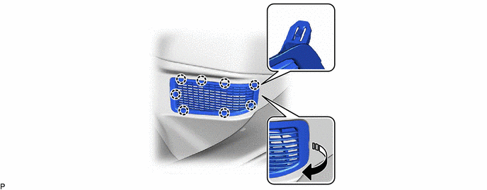
2. REMOVE NO. 1 HV BATTERY INTAKE FILTER
|
|
HINT: If the message "Maintenance Required for Traction Battery Cooling Parts See Owner's Manual" is displayed on the multi-information display, inspect the No. 1 HV battery intake filter. Click here |

Inspection
INSPECTION
PROCEDURE
1. INSPECT NO. 1 HV BATTERY INTAKE FILTER
HINT:
- If the vehicle is used in an area with heavy traffic or excessive dust, or if the rear seat is used frequently, the No. 1 HV battery intake filter may be clogged. Clean or replace the No. 1 HV battery intake filter as necessary.
- If the message "Maintenance Required for Traction Battery Cooling Parts See Owner's Manual" is not displayed on the multi-information display, clean the No. 1 HV battery intake filter with it installed to the vehicle to prevent clogs.
|
(a) Visually inspect the No. 1 HV battery intake filter. Standard: No clogs or damage. NOTICE:
If the result is not as specified, replace the No. 1 HV battery intake filter. |
|
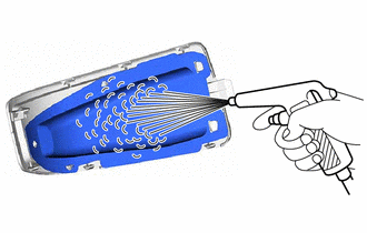
2. CLEAN NO. 1 HV BATTERY INTAKE FILTER
|
(a) Clean the No. 1 HV battery intake filter by blowing compressed air as shown in the illustration. NOTICE:
|
|
Installation
INSTALLATION
CAUTION / NOTICE / HINT
COMPONENTS (INSTALLATION)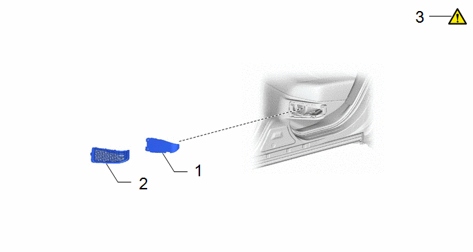
|
Procedure |
Part Name Code |
.png) |
.png) |
.png) |
|
|---|---|---|---|---|---|
|
1 |
NO. 1 HV BATTERY INTAKE FILTER |
- |
- |
- |
- |
|
2 |
BATTERY SERVICE HOLE COVER |
G92DH |
- |
- |
- |
|
3 |
CLEAR DTC |
- |
|
- |
- |
.gif)
PROCEDURE
1. INSTALL NO. 1 HV BATTERY INTAKE FILTER
2. INSTALL BATTERY SERVICE HOLE COVER
3. CLEAR DTC
|
|
HINT: If the message "Maintenance Required for Traction Battery Cooling Parts See Owner's Manual" is displayed on the multi-information display, clean or replace the No. 1 HV battery intake filter, and clear the DTCs to reset the learning values even if no DTCs are output. Click here |


