Toyota Corolla Cross: Front Fog Light Circuit
DESCRIPTION
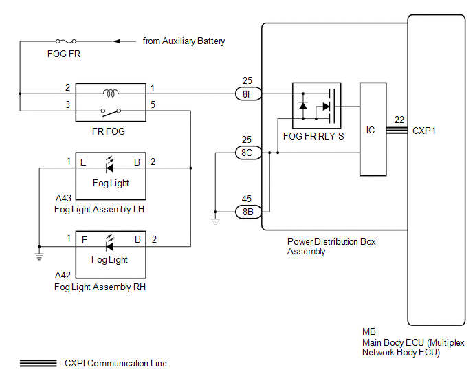
The main body ECU (multiplex network body ECU) controls the front fog lights.
WIRING DIAGRAM
CAUTION / NOTICE / HINT
NOTICE:
- Before replacing the main body ECU (multiplex network body ECU), refer to Registration.*1
Click here
.gif)
- First perform the communication function inspections in How to Proceed with Troubleshooting to confirm that there are no CXPI communication malfunctions before troubleshooting this symptom.
for HEV Model: Click here
for Gasoline Model: Click here
- *1: w/ Smart Key System
PROCEDURE
|
1. | READ VALUE USING GTS |
(a) Read the Data List according to the display on the GTS.
Body Electrical > Power Distribution Box > Data List|
Tester Display | Measurement Item |
Range | Normal Condition |
Diagnostic Note |
|---|---|---|---|---|
|
Front Fog Light External Relay Input Signal |
Front fog light external relay input |
OFF or ON | OFF: Front fog light is not input ON: Front fog light is input |
- |
|
Tester Display |
|---|
| Front Fog Light External Relay Input Signal |
OK:
Display changes according to the front fog light switch operation.
| NG | .gif) | GO TO STEP 7 |
|
.gif)
| 2. |
READ VALUE USING GTS |
(a) Using the GTS, read the Data List.
Body Electrical > Power Distribution Box > Data List|
Tester Display | Measurement Item |
Range | Normal Condition |
Diagnostic Note |
|---|---|---|---|---|
|
Front Fog Light External Relay Output Signal |
Front fog light external relay output |
OFF or ON | OFF: Front fog lights off ON: Front fog lights on |
- |
|
Tester Display |
|---|
| Front Fog Light External Relay Output Signal |
OK:
Display changes according to the front fog light switch operation.
| NG | | REPLACE POWER DISTRIBUTION BOX ASSEMBLY |
|
| 3. |
CHECK HARNESS AND CONNECTOR (POWER DISTRIBUTION BOX ASSEMBLY - BODY GROUND) |
(a) Disconnect the 8B and 8C power distribution box assembly connectors.
(b) Measure the resistance according to the value(s) in the table below.
Standard Resistance:
|
Tester Connection | Condition |
Specified Condition |
|---|---|---|
|
8C-25 - Body ground | Always |
Below 1 Ω |
|
8B-45 - Body ground | Always |
Below 1 Ω |
| NG | | REPAIR OR REPLACE HARNESS OR CONNECTOR |
|
| 4. |
INSPECT FOG FR RELAY |
HINT:
Click here
| NG | |
REPLACE FOG FR RELAY |
|
| 5. |
CHECK HARNESS AND CONNECTOR (FOG FR RELAY - FOG LIGHT ASSEMBLY) |
(a) Disconnect the A43 front fog light assembly LH connector.
(b) Disconnect the A42 front fog light assembly RH connector.
(c) Measure the resistance according to the value(s) in the table below.
Standard Resistance:
|
Tester Connection | Condition |
Specified Condition |
|---|---|---|
|
5 (FOG FR relay) - A43-2 (B) |
Always | Below 1 Ω |
|
5 (FOG FR relay) - A42-2 (B) |
Always | Below 1 Ω |
| NG | | REPAIR OR REPLACE HARNESS OR CONNECTOR |
|
| 6. |
CHECK HARNESS AND CONNECTOR (FOG LIGHT ASSEMBLY - BODY GROUND) |
(a) Measure the resistance according to the value(s) in the table below.
Standard Resistance:
|
Tester Connection | Condition |
Specified Condition |
|---|---|---|
|
A43-1 (E) - Body ground |
Always | Below 1 Ω |
|
A42-1 (E) - Body ground |
Always | Below 1 Ω |
| OK | | REPLACE POWER DISTRIBUTION BOX ASSEMBLY |
| NG | | REPAIR OR REPLACE HARNESS OR CONNECTOR |
| 7. |
CHECK HARNESS AND CONNECTOR (POWER SOURCE - FOG FR RELAY) |
(a) Remove the FOG FR relay.
(b) Measure the voltage according to the value(s) in the table below.
Standard Voltage:
|
Tester Connection | Condition |
Specified Condition |
|---|---|---|
|
2 (FOG FR relay) - Body ground |
Always | 11 to 14 V |
|
5 (FOG FR relay) - Body ground |
Always | 11 to 14 V |
| NG | | REPAIR OR REPLACE HARNESS OR CONNECTOR |
|
| 8. |
INSPECT FOG FR RELAY |
HINT:
Click here
| NG | |
REPLACE FOG FR RELAY |
|
| 9. |
CHECK HARNESS AND CONNECTOR (FOG FR RELAY - POWER DISTRIBUTION BOX ASSEMBLY) |
(a) Disconnect the 8F power distribution box assembly connector.
(b) Measure the resistance according to the value(s) in the table below.
Standard Resistance:
|
Tester Connection | Condition |
Specified Condition |
|---|---|---|
|
1 (FOG FR relay) - 8F-25 |
Always | Below 1 Ω |
| NG | | REPAIR OR REPLACE HARNESS OR CONNECTOR |
|
| 10. |
CHECK HARNESS AND CONNECTOR (FOG FR RELAY - FOG LIGHT ASSEMBLY) |
(a) Disconnect the A43 front fog light assembly LH connector.
(b) Disconnect the A42 front fog light assembly RH connector.
(c) Measure the resistance according to the value(s) in the table below.
Standard Resistance:
|
Tester Connection | Condition |
Specified Condition |
|---|---|---|
|
5 (FOG FR relay) - Body ground |
Always | 10 kΩ or higher |
|
A43-2 (B) - Body ground |
Always | 10 kΩ or higher |
|
A42-2 (B) - Body ground |
Always | 10 kΩ or higher |
| OK | | REPLACE POWER DISTRIBUTION BOX ASSEMBLY |
| NG | | REPAIR OR REPLACE HARNESS OR CONNECTOR |


