Toyota Corolla Cross: Hazard Warning Switch Circuit
DESCRIPTION
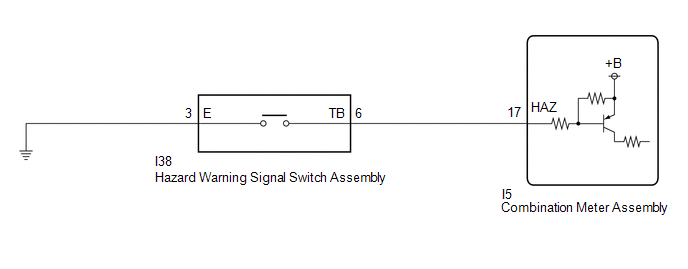
The combination meter assembly receives the hazard warning signal switch assembly on signal and controls the operation of the hazard warning lights.
WIRING DIAGRAM
CAUTION / NOTICE / HINT
NOTICE:
- When replacing the combination meter assembly, always replace it with a new one. If a combination meter assembly which was installed to another vehicle is used, the information stored in it will not match the information from the vehicle and a DTC may be stored.
- When replacing the combination meter assembly, update the ECU security key.
Click here
.gif)
PROCEDURE
|
1. | READ VALUE USING GTS |
(a) Read the Data List according to the display on the GTS.
Body Electrical > Combination Meter > Data List|
Tester Display | Measurement Item |
Range | Normal Condition |
Diagnostic Note |
|---|---|---|---|---|
|
Hazard Flasher Switch | Hazard warning signal switch signal |
OFF or ON | OFF: Hazard warning signal switch off ON: Hazard warning signal switch on |
- |
|
Tester Display |
|---|
| Hazard Flasher Switch |
OK:
Normal conditions listed above are displayed.
| OK | .gif) | PROCEED TO NEXT SUSPECTED AREA SHOWN IN PROBLEM SYMPTOMS TABLE
|
|
.gif)
| 2. |
INSPECT HAZARD WARNING SIGNAL SWITCH ASSEMBLY |
Click here
| NG | | REPLACE HAZARD WARNING SIGNAL SWITCH ASSEMBLY |
|
| 3. |
CHECK HARNESS AND CONNECTOR (HAZARD WARNING SIGNAL SWITCH ASSEMBLY - COMBINATION METER ASSEMBLY AND BODY GROUND) |
(a) Disconnect the I5 combination meter assembly connector.
(b) Measure the resistance according to the value(s) in the table below.
Standard Resistance:
|
Tester Connection | Condition |
Specified Condition |
|---|---|---|
|
I38-6 (TB) - I5-17 (HAZ) |
Always | Below 1 Ω |
|
I38-6 (TB) - Body ground |
Always | 10 kΩ or higher |
|
I5-17 (HAZ) - Body ground |
Always | 10 kΩ or higher |
|
I38-3 (E) - Body ground |
Always | Below 1 Ω |
| OK | | REPLACE COMBINATION METER ASSEMBLY
|
| NG | | REPAIR OR REPLACE HARNESS OR CONNECTOR |


