Toyota Corolla Cross: Exhaust Gas Recirculation "A" Circuit Current Below Threshold (P040318,P040319,P140018,P140019)
DESCRIPTION
Refer to DTC P040000.
Click here
.gif)
|
DTC No. | Detection Item |
DTC Detection Condition | Trouble Area |
MIL | Note |
|---|---|---|---|---|---|
|
P040318 | Exhaust Gas Recirculation "A" Circuit Current Below Threshold |
Open or short in EGR A circuit for 1 second or more (1 trip detection logic). |
| Comes on |
|
| P040319 |
Exhaust Gas Recirculation "A" Circuit Current Above Threshold |
Short in EGR A circuit for 1 second or more (1 trip detection logic). |
| Comes on |
|
| P140018 |
Exhaust Gas Recirculation "A" Control Circuit 2 Circuit Current Below Threshold |
Open or short in EGR B circuit for 1 second or more (1 trip detection logic). |
| Comes on |
|
| P140019 |
Exhaust Gas Recirculation "A" Control Circuit 2 Circuit Current Above Threshold |
Short in EGR B circuit for 1 second or more (1 trip detection logic). |
| Comes on |
|
MONITOR DESCRIPTION
These DTCs are stored if an open or short in the EGR valve assembly circuit is detected.
Example:
- If the EGA or EGB circuit terminals voltage is less than the specified value, the ECM determines that there is an open or short in the EGR valve assembly circuit, and stores a DTC P040318 or P140018.
- If the EGA or EGB circuit terminals voltage is higher than the specified value, the ECM determines that there is a short in the EGR valve assembly circuit, and stores a DTC P040319 or P140019.
MONITOR STRATEGY
|
Related DTCs | P0489: EGR A circuit range check (low voltage) P0489: EGR B circuit range check (low voltage) P0490: EGR A circuit range check (high current) P0490: EGR B circuit range check (high current) |
|
Required Sensors/Components (Main) | EGR valve assembly |
|
Required Sensors/Components (Related) |
- |
| Frequency of Operation |
Continuous |
| Duration |
1 second |
| MIL Operation |
Immediate |
| Sequence of Operation |
None |
TYPICAL ENABLING CONDITIONS
All|
Both of the following conditions are met |
- |
| Auxiliary battery voltage |
10.5 V or higher |
|
Time after ignition switch off to ON |
0.5 seconds or more |
|
Exhaust gas recirculation control circuit motor phase A high current fail (P0490) (Pending / MIL) |
Not detected |
|
Exhaust gas recirculation control circuit motor phase B high current fail (P0490) (Pending / MIL) |
Not detected |
|
Exhaust gas recirculation control circuit motor phase A low voltage fail (P0489) (Pending / MIL) |
Not detected |
|
Exhaust gas recirculation control circuit motor phase B low voltage fail (P0489) (Pending / MIL) |
Not detected |
TYPICAL MALFUNCTION THRESHOLDS
P0489: EGR A Circuit Range Check (Low Voltage)|
Either of the following conditions is met |
- |
| Motor phase A positive terminal voltage detected by motor driver IC |
0.2 V or less |
|
Motor phase A negative terminal voltage detected by motor driver IC |
0.2 V or less |
|
Either of the following conditions is met |
- |
| Motor phase B positive terminal voltage detected by motor driver IC |
0.2 V or less |
|
Motor phase B negative terminal voltage detected by motor driver IC |
0.2 V or less |
|
One of the following conditions is met | - |
|
Motor phase A positive terminal current detected by motor driver IC |
1.2 A or more |
|
Motor driver MOSFET temperature for motor phase A positive terminal detected by motor driver IC |
150°C (302°F) or higher |
|
Motor phase A negative terminal current detected by motor driver IC |
1.2 A or more |
|
Motor driver MOSFET temperature for motor phase A negative terminal detected by motor driver IC |
150°C (302°F) or higher |
|
One of the following conditions is met | - |
|
Motor phase B positive terminal current detected by motor driver IC |
1.2 A or more |
|
Motor driver MOSFET temperature for motor phase B positive terminal detected by motor driver IC |
150°C (302°F) or higher |
|
Motor phase B negative terminal current detected by motor driver IC |
1.2 A or more |
|
Motor driver MOSFET temperature for motor phase B negative terminal detected by motor driver IC |
150°C (302°F) or higher |
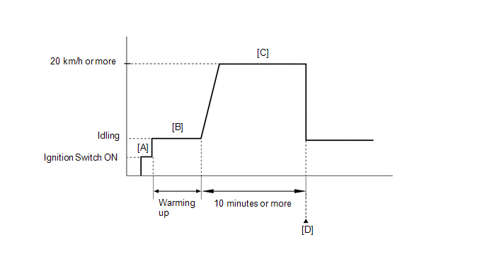
CONFIRMATION DRIVING PATTERN
HINT:
- After repair has been completed, clear the DTC and then check that the vehicle has returned to normal by performing the following All Readiness check procedure.
Click here
- When clearing the permanent DTCs, refer to the "CLEAR PERMANENT DTC" procedure.
Click here
- Connect the GTS to the DLC3.
- Turn the ignition switch to ON.
- Turn the GTS on.
- Clear the DTCs (even if no DTCs are stored, perform the clear DTC procedure).
- Turn the ignition switch off and wait for at least 30 seconds.
- Turn the ignition switch to ON [A].
- Turn the GTS on.
- Start the engine and warm it up until the engine coolant temperature reaches 75°C (167°F) or higher [B].
- Drive the vehicle at 20 km/h (12 mph) or more for 10 minutes or more [C].
CAUTION:
When performing the confirmation driving pattern, obey all speed limits and traffic laws.
- Enter the following menus: Powertrain / Engine / Trouble Codes [D].
- Read the pending DTCs.
HINT:
- If a pending DTC is output, the system is malfunctioning.
- If a pending DTC is not output, perform the following procedure.
- Enter the following menus: Powertrain / Engine / Utility / All Readiness.
- Input the DTC: P040318, P040319, P140018 or P140019.
- Check the DTC judgment result.
GTS Display
Description
NORMAL
- DTC judgment completed
- System normal
ABNORMAL
- DTC judgment completed
- System abnormal
INCOMPLETE
- DTC judgment not completed
- Perform driving pattern after confirming DTC enabling conditions
HINT:
- If the judgment result is NORMAL, the system is normal.
- If the judgment result is ABNORMAL, the system is malfunctioning.
- [A] to [D]: Normal judgment procedure.
The normal judgment procedure is used to complete DTC judgment and also used when clearing permanent DTCs.
- When clearing the permanent DTCs, do not disconnect the cable from the auxiliary battery terminal or attempt to clear the DTCs during this procedure, as doing so will clear the universal trip and normal judgment histories.
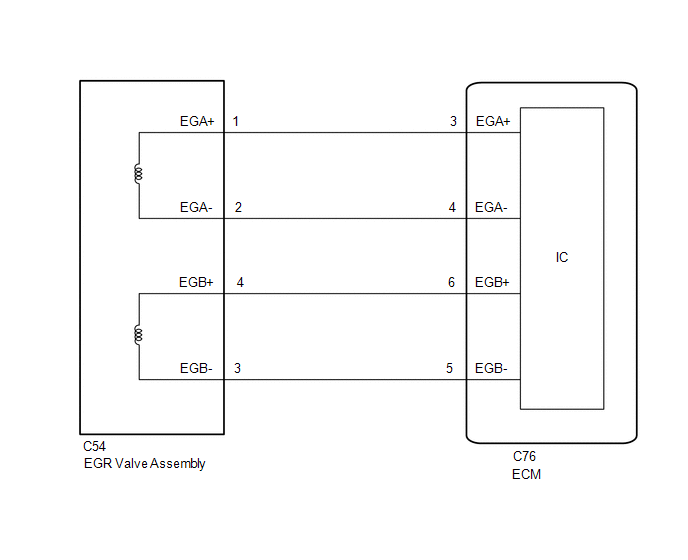
WIRING DIAGRAM
CAUTION / NOTICE / HINT
HINT:
Read Freeze Frame Data using the GTS. The ECM records vehicle and driving condition information as Freeze Frame Data the moment a DTC is stored. When troubleshooting, Freeze Frame Data can help determine if the vehicle was moving or stationary, if the engine was warmed up or not, if the air fuel ratio was lean or rich, and other data from the time the malfunction occurred.
PROCEDURE
| 1. |
PERFORM ACTIVE TEST USING GTS (CONTROL THE EGR STEP POSITION) |
(a) Start the engine and warm it up until the engine coolant temperature reaches 75°C (167°F) or higher.
HINT:
The A/C switch and all accessory switches should be off.
(b) Enter the following menus.
Powertrain > Engine > Active Test|
Active Test Display |
|---|
|
Control the EGR Step Position |
|
Data List Display |
|---|
|
Engine Speed |
|
Intake Manifold Absolute Pressure |
|
Coolant Temperature |
(c) Check the engine idling condition and Intake Manifold Absolute Pressure values in the Data List while performing the Active Test.
NOTICE:
- Do not leave the EGR valve open for 10 seconds or more during the Active Test.
- Be sure to return the EGR valve to step 0 when the Active Test is completed.
- Do not open the EGR valve 30 steps or more during the Active Test.
OK:
The value of Intake Manifold Absolute Pressure and Engine Speed change in response to EGR step position.
Standard:
|
- | Control the EGR Step Position (Active Test) | |
|---|---|---|
|
0 Steps | 0 to 30 Steps | |
|
Idling condition | Steady idling |
Idling changes from steady to rough idling or engine stalls |
|
Intake Manifold Absolute Pressure (Data List) |
Intake Manifold Absolute Pressure value is 18 to 38 kPa(abs) (2.6 to 5.5 psi(abs)) (EGR valve is fully closed) |
Intake Manifold Absolute Pressure value is at least +10 kPa (1.45 psi) higher than when EGR valve is fully closed |
HINT:
During Active Test, if the idling condition does not change in response to EGR step position, then there is probably a malfunction in the EGR valve.
| OK | .gif) | CHECK FOR INTERMITTENT PROBLEMS |
|
.gif)
| 2. |
INSPECT EGR VALVE ASSEMBLY |
Click here
HINT:
Perform "Inspection After Repair" after replacing the EGR valve assembly.
Click here
| NG | | REPLACE EGR VALVE ASSEMBLY
|
|
| 3. |
CHECK HARNESS AND CONNECTOR (EGR VALVE ASSEMBLY - ECM) |
(a) Disconnect the EGR valve assembly connector.
(b) Disconnect the ECM connector.
(c) Measure the resistance according to the value(s) in the table below.
Standard Resistance:
|
Tester Connection | Condition |
Specified Condition |
|---|---|---|
|
C54-1 (EGA+) - C76-3 (EGA+) |
Always | Below 1 Ω |
|
C54-2 (EGA-) - C76-4 (EGA-) |
Always | Below 1 Ω |
|
C54-4 (EGB+) - C76-6 (EGB+) |
Always | Below 1 Ω |
|
C54-3 (EGB-) - C76-5 (EGB-) |
Always | Below 1 Ω |
|
C54-1 (EGA+) or C76-3 (EGA+) - Body ground and other terminals |
Always | 10 kΩ or higher |
|
C54-2 (EGA-) or C76-4 (EGA-) - Body ground and other terminals |
Always | 10 kΩ or higher |
|
C54-4 (EGB+) or C76-6 (EGB+) - Body ground and other terminals |
Always | 10 kΩ or higher |
|
C54-3 (EGB-) or C76-5 (EGB-) - Body ground and other terminals |
Always | 10 kΩ or higher |
| OK | | REPLACE ECM
|
| NG | | REPAIR OR REPLACE HARNESS OR CONNECTOR |


