Toyota Corolla Cross: EVAP System Switching Valve Control Circuit "B" High Circuit Short to Battery (P14CE12,P14CE14,P241812,P241814)
DESCRIPTION
Refer to EVAP (Evaporative Emission) System.
Click here .gif)
|
DTC No. | Detection Item |
DTC Detection Condition | Trouble Area |
MIL | Note |
|---|---|---|---|---|---|
|
P14CE12 | EVAP System Switching Valve Control Circuit "B" High Circuit Short to Battery |
Short in CCV B circuit for 0.5 seconds or more (1 trip detection logic). |
|
|
|
| P14CE14 |
EVAP System Switching Valve Control Circuit "B" Low Circuit Short to Ground or Open |
Open or short in CCV B circuit for 0.5 seconds or more (1 trip detection logic). |
|
|
|
| P241812 |
EVAP System Switching Valve Control Circuit High Circuit Short to Battery |
Short in CCV A circuit for 0.5 seconds or more (1 trip detection logic). |
| Comes on |
|
| P241814 |
EVAP System Switching Valve Control Circuit Low Circuit Short to Ground or Open |
Open or short in CCV A circuit for 0.5 seconds or more (1 trip detection logic). |
| Comes on |
|
|
DTC No. | Monitoring Item |
Detection Timing | Detection Logic |
SAE Code |
|---|---|---|---|---|
| P14CE12 |
CCV B circuit range check (high current) |
Always | 1 trip |
P14D1 |
| P14CE14 |
CCV B circuit range check (low voltage) |
P14D0 | ||
| P241812 |
CCV A circuit range check (high current) |
P2420 | ||
| P241814 |
CCV A circuit range check (low voltage) |
P2419 |
MONITOR DESCRIPTION
These DTCs are stored if an open or short in the fuel vapor-containment valve circuit is detected.
Example:
- If the CCA+, CCA-, CCB+ or CCB- operation signal is off, but the step motor output signal is on, the ECM determines that there is a short in the fuel vapor-containment valve circuit, and stores a DTC P14CE12 or P241812.
- If the CCA+, CCA-, CCB+ or CCB- operation signal is on, and the step motor output signal is off, the ECM determines that there is an open or short in the fuel vapor-containment valve circuit, and stores a DTC P14CE14 or P241814.
MONITOR STRATEGY
|
Required Sensors/Components (Main) | Fuel vapor-containment valve |
|
Required Sensors/Components (Related) |
- |
| Frequency of Operation |
Continuous |
| Duration |
0.5 seconds |
| MIL Operation |
Immediate |
| Sequence of Operation |
None |
TYPICAL ENABLING CONDITIONS
|
Monitor runs whenever the following DTCs are not stored |
None |
| Auxiliary battery voltage |
10 V or higher |
TYPICAL MALFUNCTION THRESHOLDS
P14D0|
Both of the following conditions are met |
- |
| Command to motor phase B |
OFF |
| Either of the following conditions is met |
A or B |
| A. Motor phase B positive terminal voltage level |
Low |
| B. Motor phase B negative terminal voltage level |
Low |
|
Either of the following conditions is met |
A or B |
| A. Motor phase B positive terminal current detected by motor driver IC |
2.5 A or more |
|
B. Motor phase B negative terminal current detected by motor driver IC |
2.5 A or more |
|
Both of the following conditions are met |
- |
| Command to motor phase A |
OFF |
| Either of the following conditions is met |
A or B |
| A. Motor phase A positive terminal voltage level |
Low |
| B. Motor phase A negative terminal voltage level |
Low |
|
Either of the following conditions is met |
A or B |
| A. Motor phase A positive terminal current detected by motor driver IC |
2.5 A or more |
|
B. Motor phase A negative terminal current detected by motor driver IC |
2.5 A or more |
CONFIRMATION DRIVING PATTERN
HINT:
- After repair has been completed, clear the DTC and then check that the vehicle has returned to normal by performing the following All Readiness check procedure.
Click here
- When clearing the permanent DTCs, refer to the "CLEAR PERMANENT DTC" procedure.
Click here
- Connect the GTS to the DLC3.
- Turn the ignition switch to ON.
- Turn the GTS on.
- Clear the DTCs (even if no DTCs are stored, perform the clear DTC procedure).
- Turn the ignition switch off and wait for at least 30 seconds.
- Turn the ignition switch to ON.
- Turn the GTS on.
- Wait 5 seconds or more [A].
- Enter the following menus: Powertrain / Engine / Trouble Codes [B].
- Read the pending DTCs.
HINT:
- If a pending DTC is output, the system is malfunctioning.
- If a pending DTC is not output, perform the following procedure.
- Enter the following menus: Powertrain / Engine / Utility / All Readiness.
- Input the DTC: P14CE12, P14CE14, P241812 or P241814.
- Check the DTC judgment result.
GTS Display
Description
NORMAL
- DTC judgment completed
- System normal
ABNORMAL
- DTC judgment completed
- System abnormal
INCOMPLETE
- DTC judgment not completed
- Perform driving pattern after confirming DTC enabling conditions
HINT:
- If the judgment result is NORMAL, the system is normal.
- If the judgment result is ABNORMAL, the system is malfunctioning.
- If the judgment result is INCOMPLETE, perform the steps [A] through [B] again.
- [A] to [B]: Normal judgment procedure.
The normal judgment procedure is used to complete DTC judgment and also used when clearing permanent DTCs.
- When clearing the permanent DTCs, do not disconnect the cable from the auxiliary battery terminal or attempt to clear the DTCs during this procedure, as doing so will clear the universal trip and normal judgment histories.
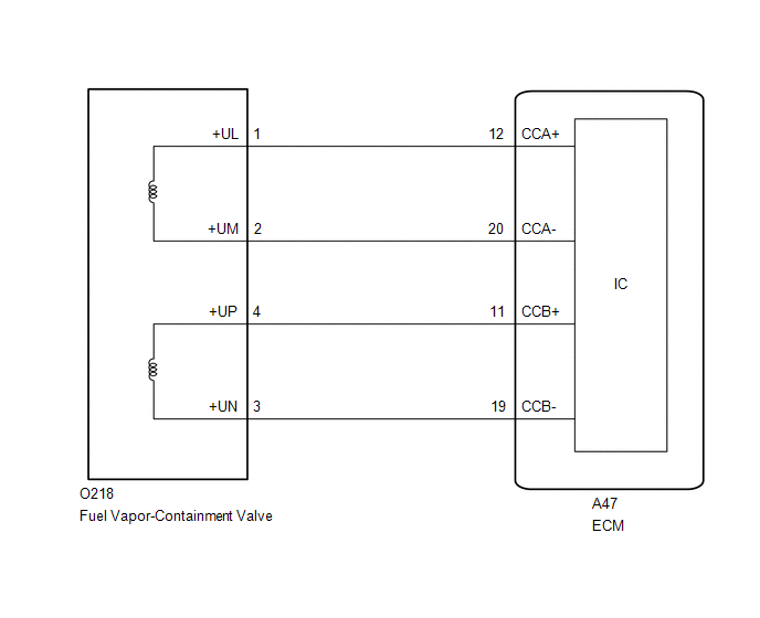
WIRING DIAGRAM
CAUTION / NOTICE / HINT
NOTICE:
- Vehicle Control History may be stored in the hybrid vehicle control ECU if the engine is malfunctioning. Certain vehicle condition information is recorded when Vehicle Control History is stored. Reading the vehicle conditions recorded in both the freeze frame data and Vehicle Control History can be useful for troubleshooting.
Click here
(Select Powertrain in Health Check and then check the time stamp data.)
- If any "Engine Malfunction" Vehicle Control History item has been stored in the hybrid vehicle control ECU, make sure to clear it. However, as all Vehicle Control History items are cleared simultaneously, if any Vehicle Control History items other than "Engine Malfunction" are stored, make sure to perform any troubleshooting for them before clearing Vehicle Control History.
Click here
HINT:
- Read Freeze Frame Data using the GTS. The ECM records vehicle and driving condition information as Freeze Frame Data the moment a DTC is stored. When troubleshooting, Freeze Frame Data can help determine if the vehicle was moving or stationary, if the engine was warmed up or not, if the air fuel ratio was lean or rich, and other data from the time the malfunction occurred.
- If the cable is disconnected from the Auxiliary Battery terminal, the fuel vapor containment valve cannot close completely and an EVAP SYSTEM DTC will be stored. If the DTC is output, drive the vehicle at a speed of 10 km/h (6 mph) or more and then leave the vehicle for 30 seconds or more. Then perform the Evaporative System Check again.
PROCEDURE
|
1. | CLEAR DTC |
(a) Clear the DTC after recording the Freeze Frame Data and DTC.
Powertrain > Engine > Clear DTCs(b) Turn the ignition switch off and wait for at least 30 seconds.
|
.gif)
| 2. |
READ OUTPUT DTC (IN ADDITION TO DTC P14CE12, P14CE14, P241812 OR P241814) |
(a) Read the DTCs.
Powertrain > Engine > Trouble Codes|
Result | Proceed to |
|---|---|
|
DTC P14CE12, P14CE14, P241812 or P241814 is output |
A |
| DTCs are not output |
B |
| B |
.gif) | CHECK FOR INTERMITTENT PROBLEMS |
|
| 3. |
CHECK HARNESS AND CONNECTOR |
(a) Disconnect the ECM connector.
(b) Measure the resistance according to the value(s) in the table below.
Standard Resistance:
|
Tester Connection | Condition |
Specified Condition |
|---|---|---|
|
A47-12 (CCA+) - A47-20 (CCA-) |
20°C (68°F) | 29 to 33 Ω |
|
A47-11 (CCB+) - A47-19 (CCB-) |
20°C (68°F) | 29 to 33 Ω |
|
A47-12 (CCA+) or A47-20 (CCA-) - Body ground and other terminals |
Always | 10 kΩ or higher |
|
A47-11 (CCB+) or A47-19 (CCB-) - Body ground and other terminals |
Always | 10 kΩ or higher |
HINT:
The standard values shown are fuel vapor-containment valve resistance values.
| OK | | REPLACE ECM |
|
| 4. |
INSPECT FUEL VAPOR CONTAINMENT VALVE |
Click here
| OK | |
REPAIR OR REPLACE HARNESS OR CONNECTOR (FUEL VAPOR-CONTAINMENT VALVE - ECM) |
| NG | | REPLACE FUEL VAPOR CONTAINMENT VALVE |
READ NEXT:
 Actuator Cut Circuit Stuck Off (P16B09F)
MONITOR DESCRIPTION The ECM monitors the operation of the throttle actuator. When a malfunction is detected in the throttle actuator cut circuit immediately after the ignition switch is turned off, th
Throttle Actuator "A" Control Motor Circuit Current Below Threshold (P210018,P210019)
DESCRIPTION The throttle actuator is operated by the ECM and opens and closes the throttle valve using gears.
The opening angle of the throttle valve is detected by the throttle position sensor, whi
Throttle/Pedal Position Sensor "A" Minimum Stop Performance (P210900)
DESCRIPTION The idle speed is controlled by the Electronic Throttle Control System (ETCS). The ETCS is comprised of a throttle actuator, which operates the throttle valve, and a throttle position sens
SEE MORE:
 Installation
INSTALLATION
CAUTION / NOTICE / HINT
COMPONENTS (INSTALLATION)
Procedure
Part Name Code
1
TRANSMISSION REVOLUTION SENSOR (NOUT)
89413M
-
-
N*m
Gear Shift Position Circuit Short to Battery (P091412)
DESCRIPTION
A magnet is installed to the shift fork. When the TCM commands the S1 synchronizer
to move, the shift fork moves the S1 synchronizer together and the magnet.
The Hall IC built into the shift stroke sensor converts the magnet position into
a voltage signal and sends it to the TCM. T
