Toyota Corolla Cross: Throttle / Pedal Position Sensor / Switch "A" Circuit Short to Ground (P012011)
DESCRIPTION
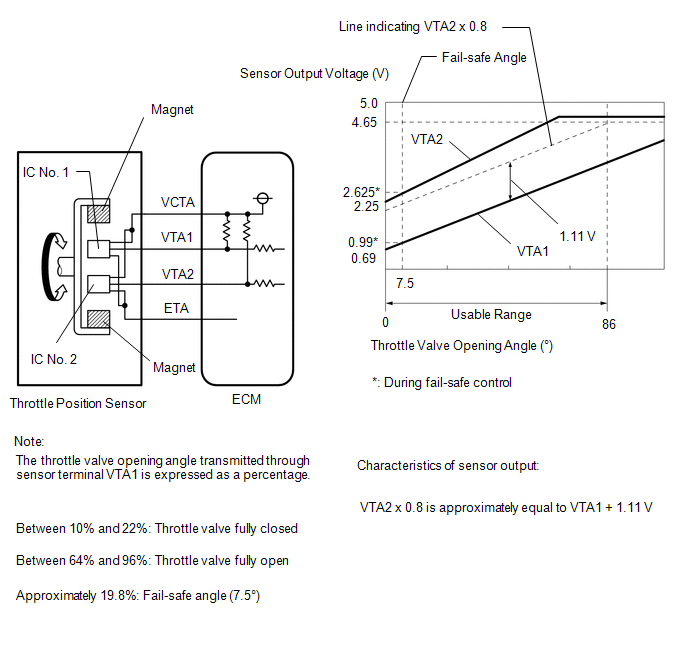
The throttle position sensor is built into the throttle body with motor assembly and detects the opening angle of the throttle valve. This sensor is a non-contact type sensor. It uses Hall-effect elements in order to yield accurate signals even in extreme driving conditions, such as at high speeds as well as very low speeds.
The throttle position sensor has 2 sensor circuits, VTA1 and VTA2, each of which transmits a signal. VTA1 is used to detect the throttle valve angle and VTA2 is used to detect malfunctions in VTA1. The sensor signal voltages vary between 0 V and 5 V in proportion to the throttle valve opening angle, and are transmitted to the VTA1 and VTA2 terminals of the ECM.
As the valve closes, the sensor output voltage decreases and as the valve opens, the sensor output voltage increases. The ECM calculates the throttle valve opening angle according to these signals and controls the throttle actuator in response to driver inputs. These signals are also used in calculations such as air fuel ratio correction, power increase correction and fuel-cut control.
HINT:
- When throttle position sensor DTCs are output, check the throttle valve opening angle using the GTS. Enter the following menus: Powertrain / Engine / Data List / Throttle Position Sensor No.1 Voltage and Throttle Position Sensor No.2 Voltage.
- Throttle Position Sensor No.1 Voltage is the VTA1 signal, and Throttle Position Sensor No.2 Voltage is the VTA2 signal.
Reference (Normal Condition):
When Accelerator Pedal Fully Released
When Accelerator Pedal Fully Depressed
(Engine Running)
Throttle Position Sensor No.1 Voltage (VTA1)
Throttle Position Sensor No.2 Voltage (VTA2)
Throttle Position Sensor No.1 Voltage (VTA1)
Throttle Position Sensor No.2 Voltage (VTA2)
0.6 to 1.1 V
2.1 to 3.1 V
3.2 to 4.8 V
(Not fail-safe)
4.6 to 4.98 V
(Not fail-safe)
|
DTC No. | Detection Item |
DTC Detection Condition | Trouble Area |
MIL | Note |
|---|---|---|---|---|---|
|
P012011 | Throttle / Pedal Position Sensor / Switch "A" Circuit Short to Ground |
The output voltage of VTA1 is less than 0.56 V for 2 seconds or more (1 trip detection logic). |
| Comes on |
|
MONITOR DESCRIPTION
The ECM uses the throttle position sensor to monitor the throttle valve opening angle. If the VTA1 terminal voltage is less than the threshold, the ECM will illuminate the MIL and store this DTC.
MONITOR STRATEGY
|
Related DTCs | P0122: Throttle position sensor 1 range check (low voltage) |
|
Required Sensors/Components (Main) | Throttle position sensor |
|
Required Sensors/Components (Related) | - |
|
Frequency of Operation | Continuous |
|
Duration | 2 seconds |
| MIL Operation |
Immediate |
| Sequence of Operation |
None |
TYPICAL ENABLING CONDITIONS
|
Monitor runs whenever the following DTCs are not stored |
None |
| Both of the following conditions are met |
- |
| Auxiliary battery voltage |
8 V or higher |
| Ignition switch |
ON |
TYPICAL MALFUNCTION THRESHOLDS
|
VTA1 voltage | Less than 0.56 V |
CONFIRMATION DRIVING PATTERN
HINT:
- After repair has been completed, clear the DTC and then check that the vehicle has returned to normal by performing the following All Readiness check procedure.
Click here
.gif)
- When clearing the permanent DTCs, refer to the "CLEAR PERMANENT DTC" procedure.
Click here
- Connect the GTS to the DLC3.
- Turn the ignition switch to ON.
- Turn the GTS on.
- Clear the DTCs (even if no DTCs are stored, perform the clear DTC procedure).
- Turn the ignition switch off and wait for at least 30 seconds.
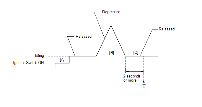
- Turn the ignition switch to ON [A].
- Turn the GTS on.
- Start the engine.
- With the vehicle stationary, fully depress and release the accelerator pedal [B].
- Idle the engine for 2 seconds or more [C].
- Enter the following menus: Powertrain / Engine / Trouble Codes [D].
- Read the pending DTCs.
HINT:
- If a pending DTC is output, the system is malfunctioning.
- If a pending DTC is not output, perform the following procedure.
- Enter the following menus: Powertrain / Engine / Utility / All Readiness.
- Input the DTC: P012011.
- Check the DTC judgment result.
GTS Display
Description
NORMAL
- DTC judgment completed
- System normal
ABNORMAL
- DTC judgment completed
- System abnormal
INCOMPLETE
- DTC judgment not completed
- Perform driving pattern after confirming DTC enabling conditions
HINT:
- If the judgment result is NORMAL, the system is normal.
- If the judgment result is ABNORMAL, the system is malfunctioning.
- If the judgment result is INCOMPLETE, perform steps [B] through [D] again.
- [A] to [D]: Normal judgment procedure.
The normal judgment procedure is used to complete DTC judgment and also used when clearing permanent DTCs.
- When clearing the permanent DTCs, do not disconnect the cable from the auxiliary battery terminal or attempt to clear the DTCs during this procedure, as doing so will clear the universal trip and normal judgment histories.
FAIL-SAFE
When this DTC is stored, the ECM enters fail-safe mode. During fail-safe mode, the ECM cuts the current to the throttle actuator, and the throttle valve is returned to a 7.5° throttle valve opening angle by the return spring. The ECM then adjusts the engine output by controlling the fuel injection (intermittent fuel-cut) and ignition timing, in accordance with the accelerator pedal angle, to allow the vehicle to continue running at a minimal speed. If the accelerator pedal is depressed firmly and gently, the vehicle can be driven slowly.
Fail-safe mode continues until a pass condition is detected, and the ignition switch is turned off.
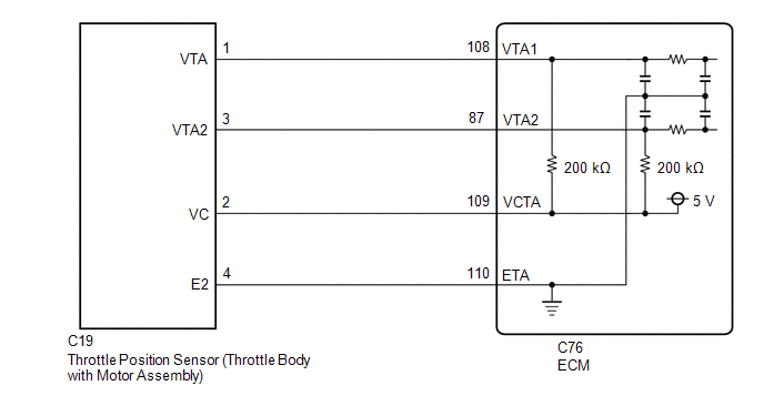
WIRING DIAGRAM
CAUTION / NOTICE / HINT
HINT:
Read Freeze Frame Data using the GTS. The ECM records vehicle and driving condition information as Freeze Frame Data the moment a DTC is stored. When troubleshooting, Freeze Frame Data can help determine if the vehicle was moving or stationary, if the engine was warmed up or not, if the air fuel ratio was lean or rich, and other data from the time the malfunction occurred.
PROCEDURE
| 1. |
READ VALUE USING GTS (THROTTLE POSITION SENSOR NO.1 VOLTAGE) |
(a) Enter the following menus.
Powertrain > Engine > Data List|
Tester Display |
|---|
| Throttle Position Sensor No.1 Voltage |
(b) Read the values displayed on the GTS.
(c) Disconnect the throttle body with motor assembly connector.
(d) Compare the value of the Data List item Throttle Position Sensor No.1 Voltage after disconnecting the throttle body with motor assembly connector to the value when the connector was connected.
|
Result | Proceed to |
|---|---|
|
Changes from less than 0.56 V to higher than 4.535 V |
A |
| Does not change from less than 0.56 V |
B |
HINT:
Perform "Inspection After Repair" after replacing the throttle body with motor assembly.
Click here
| A |
.gif) | REPLACE THROTTLE BODY WITH MOTOR ASSEMBLY |
|
.gif)
| 2. |
CHECK HARNESS AND CONNECTOR (THROTTLE POSITION SENSOR - ECM) |
(a) Disconnect the throttle body with motor assembly connector.
(b) Disconnect the ECM connector.
(c) Measure the resistance according to the value(s) in the table below.
Standard Resistance:
|
Tester Connection | Condition |
Specified Condition |
|---|---|---|
|
C19-2 (VC) - C76-109 (VCTA) |
Always | Below 1 Ω |
|
C19-1 (VTA) or C76-108 (VTA1) - Body ground |
Always | 10 kΩ or higher |
| OK | | REPLACE ECM
|
| NG | | REPAIR OR REPLACE HARNESS OR CONNECTOR |


