Toyota Corolla Cross: Engine Coolant Pump Circuit Short to Battery (P26CA12)
DESCRIPTION
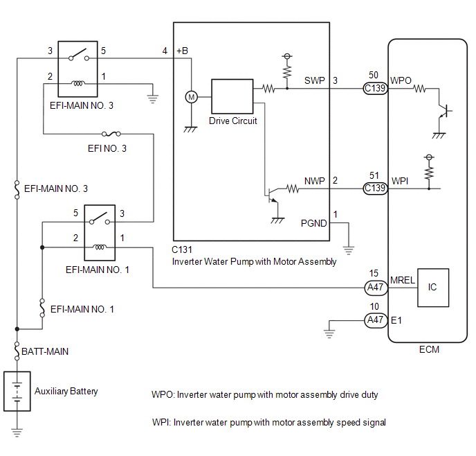
The ECM calculates the necessary cooling amount based on the engine coolant temperature, engine speed and vehicle speed, and controls the inverter water pump with motor assembly accordingly. The inverter water pump with motor assembly controls the speed of the inverter water pump with motor assembly steplessly and optimally based on a duty cycle signal sent by the ECM, which reduces engine warm-up time, improves fuel efficiency and reduces cooling loss.
|
DTC No. | Detection Item |
DTC Detection Condition | Trouble Area |
MIL | Note |
|---|---|---|---|---|---|
|
P26CA12 | Engine Coolant Pump Circuit Short to Battery |
The operation duty ratio signal (WPO) of the inverter water pump with motor assembly is a certain value or more when the inverter water pump with motor assembly operation signal is being output (1 trip detection logic). |
| Comes on |
|
|
DTC No. | Data List |
|---|---|
|
P26CA12 |
|
MONITOR DESCRIPTION
The ECM outputs an operation duty signal (WPO) to steplessly control the speed of the inverter water pump with motor assembly. The ECM outputs an operation duty signal (WPO) to the inverter water pump with motor assembly and monitors the actual duty signal (WPO) being output. When the actual operation duty signal (WPO) exceeds a certain value when outputting an operation duty signal (WPO) to the inverter water pump with motor assembly, the ECM detects a malfunction and stores a DTC.
MONITOR STRATEGY
|
Related DTCs | P26CD: Engine water pump circuit range check (High voltage) |
|
Required Sensors/Components (Main) | Water inlet housing with water pump sub-assembly |
|
Required Sensors/Components (Related) |
- |
| Frequency of Operation |
Continuous |
| Duration |
3 seconds |
| MIL Operation |
Immediate |
| Sequence of Operation |
None |
TYPICAL ENABLING CONDITIONS
|
All of the following conditions are met |
- |
| Auxiliary battery voltage |
8 V or higher |
|
Ignition switch | ON |
|
Time after ignition switch off to ON |
0.5 seconds or more |
|
Output duty cycle | 30 to 85% |
|
Engine water pump circuit pulse input fail (P26CA) |
Not detected |
TYPICAL MALFUNCTION THRESHOLDS
|
Both of the following conditions are met |
- |
| Water inlet housing with water pump sub-assembly output terminal voltage level |
High |
| Water inlet housing with water pump sub-assembly output signal |
No signal |
CONFIRMATION DRIVING PATTERN
HINT:
- After repair has been completed, clear the DTC and then check that the vehicle has returned to normal by performing the following All Readiness check procedure.
Click here
.gif)
- When clearing the permanent DTCs, refer to the "CLEAR PERMANENT DTC" procedure.
Click here
- Connect the GTS to the DLC3.
- Turn the ignition switch to ON.
- Turn the GTS on.
- Clear the DTCs (even if no DTCs are stored, perform the clear DTC procedure).
- Turn the ignition switch off and wait for at least 30 seconds.
- Turn the ignition switch to ON [A].
- Turn the GTS on.
- Put the engine in Inspection Mode (Maintenance Mode).
Click here
- Start the engine and maintain the engine speed at 2500 rpm or more for at least 40 seconds [B].
- Enter the following menus: Powertrain / Engine / Trouble Codes [C].
- Read the pending DTCs.
HINT:
- If a pending DTC is output, the system is malfunctioning.
- If a pending DTC is not output, perform the following procedure.
- Enter the following menus: Powertrain / Engine / Utility / All Readiness.
- Input the DTC: P26CA12.
- Check the DTC judgment result.
GTS Display
Description
NORMAL
- DTC judgment completed
- System normal
ABNORMAL
- DTC judgment completed
- System abnormal
INCOMPLETE
- DTC judgment not completed
- Perform driving pattern after confirming DTC enabling conditions
HINT:
- If the judgment result is NORMAL, the system is normal.
- If the judgment result is ABNORMAL, the system has a malfunction.
- If the judgment result is INCOMPLETE, perform steps [B] through [C] again.
- [A] to [C]: Normal judgment procedure.
The normal judgment procedure is used to complete DTC judgment and also used when clearing permanent DTCs.
- When clearing the permanent DTCs, do not disconnect the cable from the auxiliary battery terminal or attempt to clear the DTCs during this procedure, as doing so will clear the universal trip and normal judgment histories.
WIRING DIAGRAM
CAUTION / NOTICE / HINT
NOTICE:
- Vehicle Control History may be stored in the hybrid vehicle control ECU assembly if the engine is malfunctioning. Certain vehicle condition information is recorded when Vehicle Control History is stored. Reading the vehicle conditions recorded in both the freeze frame data and Vehicle Control History can be useful for troubleshooting.
Click here
(Select Powertrain in Health Check and then check the time stamp data.)
- If any "Engine Malfunction" Vehicle Control History item has been stored in the hybrid vehicle control ECU assembly, make sure to clear it. However, as all Vehicle Control History items are cleared simultaneously, if any Vehicle Control History items other than "Engine Malfunction" are stored, make sure to perform any troubleshooting for them before clearing Vehicle Control History.
Click here
HINT:
Read Freeze Frame Data using the GTS. The ECM records vehicle and driving condition information as Freeze Frame Data the moment a DTC is stored. When troubleshooting, Freeze Frame Data can help determine if the vehicle was moving or stationary, if the engine was warmed up or not, if the air fuel ratio was lean or rich, and other data from the time the malfunction occurred.
PROCEDURE
| 1. |
CHECK TERMINAL VOLTAGE (POWER SOURCE OF INVERTER WATER PUMP WITH MOTOR ASSEMBLY) |
|
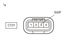
*a | Front view of wire harness connector (to Inverter Water Pump with Motor Assembly) |
(a) Disconnect the inverter water pump with motor assembly connector.
(b) Turn the ignition switch to ON.
(c) Measure the voltage according to the value(s) in the table below.
Standard Voltage:
|
Tester Connection | Condition |
Specified Condition |
|---|---|---|
|
C131-3 (SWP) - Body ground |
Ignition switch ON | Below 1 V |
| NG | .gif) | GO TO STEP 3 |
|
.gif)
| 2. |
INSPECT ECM (INTERNAL CIRCUIT) |
|
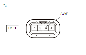
*a | Front view of wire harness connector (to Inverter Water Pump with Motor Assembly) |
(a) Disconnect the inverter water pump with motor assembly connector.
(b) Turn the ignition switch to ON.
(c) Perform the Active Test using the GTS.
Powertrain > Engine > Active Test|
Tester Display |
|---|
| Activate the Electric Water Pump |
(d) Measure the resistance according to the value(s) in the table below.
Standard:
|
Tester Connection | Condition |
Specified Condition |
|---|---|---|
|
C131-3 (SWP) - Body ground |
During Active Test | Resistance fluctuates* |
HINT:
- *: When the connector of the inverter water pump with motor assembly is disconnected, the ECM will enter fail-safe mode. In this case, duty control of the transistors in the ECM will be performed and resistance fluctuates.
- If the resistance fluctuates while the ECM is in fail-safe mode after the connector of the inverter water pump with motor assembly is disconnected, it can be determined that the transistor is operating.
- If the transistor does not operate, the ECM may be malfunctioning.
- If the resistance fluctuates after turning the ignition switch to ON, it can be determined that the ECM is in fail-safe mode.
| OK | | REPLACE INVERTER WATER PUMP WITH MOTOR ASSEMBLY |
| NG | | REPLACE ECM |
| 3. |
CHECK HARNESS AND CONNECTOR (INVERTER WATER PUMP WITH MOTOR ASSEMBLY - ECM) |
(a) Disconnect the inverter water pump with motor assembly connector.
(b) Disconnect the ECM connector.
(c) Measure the resistance according to the value(s) in the table below.
Standard Resistance:
|
Tester Connection | Condition |
Specified Condition |
|---|---|---|
|
C131-3 (SWP) or C139-50 (WPO) - Other terminals |
Always | 10 kΩ or higher |
| OK | | REPLACE ECM |
| NG | | REPAIR OR REPLACE HARNESS OR CONNECTOR |


