Toyota Corolla Cross: Removal
REMOVAL
CAUTION / NOTICE / HINT
COMPONENTS (REMOVAL)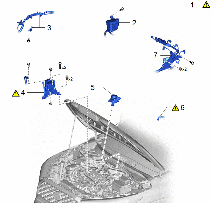
|
Procedure | Part Name Code |
.png) |
.png) |
 |
|---|---|---|---|---|---|
|
1 | ENGINE SUPPORT BRIDGE |
- |
|
- | - |
|
2 | RADIATOR RESERVE TANK ASSEMBLY |
16470 | - |
- | - |
|
3 | NO. 1 COOLER REFRIGERANT HOSE |
- | - |
- | - |
|
4 | ENGINE MOUNTING INSULATOR SUB-ASSEMBLY RH |
12305 |
|
- | - |
|
5 | FUEL(ENGINE ROOM SIDE) PUMP ASSEMBLY |
23100X | - |
- | - |
|
6 | NO. 1 VACUUM HOSE CONNECTOR |
44777 |
|
- | - |
|
7 | ENGINE WIRE |
82121 | - |
- | - |
|
Procedure | Part Name Code |
|
|
| |
|---|---|---|---|---|---|
|
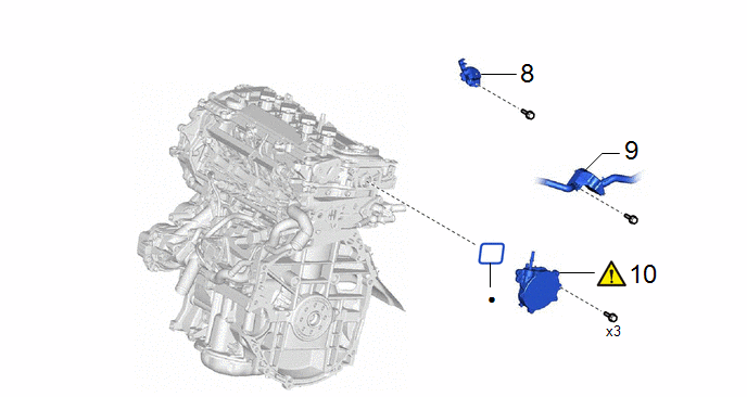
8 | VACUUM SURGE TANK |
25719 | - |
- | - |
|
9 | NO. 3 WATER HOSE CLAMP BRACKET |
16575F | - |
- | - |
|
10 | VACUUM PUMP ASSEMBLY |
29300 |
|
- | - |
|
● | Non-reusable part |
- | - |
|
Procedure | Part Name Code |
|
|
| |
|---|---|---|---|---|---|
|
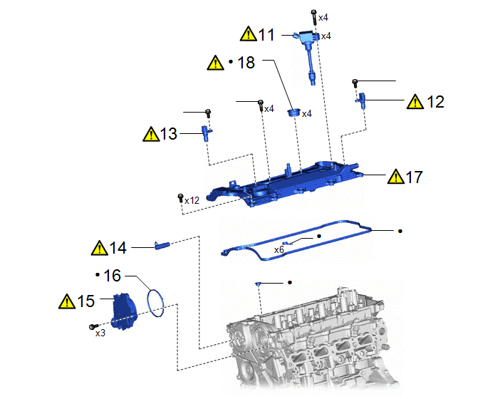
11 | IGNITION COIL ASSEMBLY |
19500 |
|
- | - |
|
12 | CAMSHAFT POSITION SENSOR (for Intake Side) |
11102A |
|
- | - |
|
13 | CAMSHAFT POSITION SENSOR (for Exhaust Side) |
11102A |
|
- | - |
|
14 | CAMSHAFT TIMING OIL CONTROL VALVE ASSEMBLY (EXHAUST CAMSHAFT TIMING GEAR BOLT ASSEMBLY) |
135A0A |
|
- | - |
|
15 | CAM TIMING CONTROL MOTOR WITH EDU ASSEMBLY |
13090D |
|
- | - |
|
16 | CAM TIMING CONTROL MOTOR O-RING |
13090E | - |
- | - |
|
17 | CYLINDER HEAD COVER SUB-ASSEMBLY |
11201 |
|
- | - |
|
18 | SPARK PLUG TUBE GASKET |
11193 |
|
- | - |
|
● | Non-reusable part |
★ | Precoated part |
|
Procedure | Part Name Code |
|
|
| |
|---|---|---|---|---|---|
|
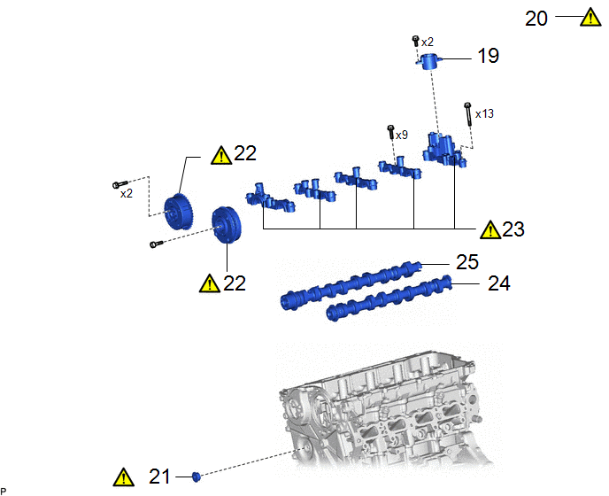
19 | FUEL PUMP LIFTER GUIDE |
23477 | - |
- | - |
|
20 | NO. 1 CYLINDER TO TDC (COMPRESSION) |
- |
|
- | - |
|
21 | STRAIGHT SCREW PLUG |
- |
|
- | - |
|
22 | CAMSHAFT TIMING GEAR |
- |
|
- | - |
|
23 | CAMSHAFT BEARING CAP |
- |
|
- | - |
|
24 | INTAKE CAMSHAFT SUB-ASSEMBLY |
- | - |
- | - |
|
25 | EXHAUST CAMSHAFT SUB-ASSEMBLY |
- | - |
- | - |
|
★ | Precoated part |
- | - |
CAUTION / NOTICE / HINT
The necessary procedures (adjustment, calibration, initialization or registration) that must be performed after parts are removed and installed, or replaced during camshaft removal/installation are shown below.
Necessary Procedures After Parts Removed/Installed/Replaced|
Replaced Part or Performed Procedure |
Necessary Procedure | Effect/Inoperative Function when Necessary Procedure not Performed |
Link |
|---|---|---|---|
| Inspection After Repair |
|
|
NOTICE:
- After the ignition switch is turned off, the radio and display receiver assembly records various types of memory and settings. As a result, after turning the ignition switch off, make sure to wait at least 120 seconds before disconnecting the cable from the negative (-) battery terminal.
- This procedure includes the removal of small-head bolts. Refer to Small-Head Bolts of Basic Repair Hint to identify the small-head bolts.
Click here
.gif)
HINT:
When the cable is disconnected/reconnected to the auxiliary battery terminal, systems temporarily stop operating. However, each system has a function that completes learning the first time the system is used.
- Learning completes when vehicle is driven.
Effect/Inoperative Function When Necessary Procedures are not Performed
Necessary Procedures
Link
Front camera system
Drive the vehicle straight ahead at 15 km/h (10 mph) or more for 1 second or more.
Stop and start system
Drive the vehicle until stop and start control is permitted (approximately 5 to 60 minutes)
- Learning completes when vehicle is operated normally
Effect/Inoperative Function When Necessary Procedures are not Performed
Necessary Procedures
Link
Power door lock control system
- Back door opener
Perform door unlock operation with door control switch or electrical key transmitter sub-assembly switch.
Power back door system
Fully close the back door by hand.
HINT:
Initialization is not necessary if the above procedures are performed while the back door is closed.
Air conditioning system
After the ignition switch is turned to ON, the servo motor standard position is recognized.
-
PROCEDURE
1. INSTALL ENGINE SUPPORT BRIDGE
Click here
2. SEPARATE RADIATOR RESERVE TANK ASSEMBLY
Click here
3. SEPARATE NO. 1 COOLER REFRIGERANT HOSE
Click here
4. REMOVE ENGINE MOUNTING INSULATOR SUB-ASSEMBLY RH
|
|
Click here |
5. REMOVE FUEL (ENGINE ROOM SIDE) PUMP ASSEMBLY (for High Pressure)
Click here
6. DISCONNECT NO. 1 VACUUM HOSE CONNECTOR
|
|
Click here |
7. SEPARATE ENGINE WIRE
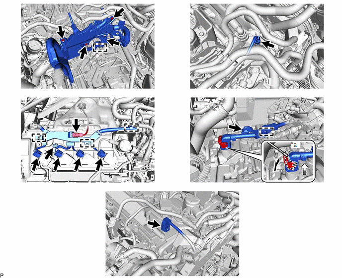
|
*a | Protective Tape |
- | - |
.png) |
Release the lock lever |
.png) |
Disconnect the connector |
8. REMOVE VACUUM SURGE TANK

9. REMOVE NO. 3 WATER HOSE CLAMP BRACKET

10. REMOVE VACUUM PUMP ASSEMBLY
|
|
Click here |
11. REMOVE IGNITION COIL ASSEMBLY
Click here
12. REMOVE CAMSHAFT POSITION SENSOR (for Intake Side)
Click here
13. REMOVE CAMSHAFT POSITION SENSOR (for Exhaust Side)
Click here
14. REMOVE CAMSHAFT TIMING OIL CONTROL VALVE ASSEMBLY (EXHAUST CAMSHAFT TIMING GEAR BOLT ASSEMBLY)
Click here
15. REMOVE CAM TIMING CONTROL MOTOR WITH EDU ASSEMBLY
Click here
16. REMOVE CAM TIMING CONTROL MOTOR O-RING
Click here
17. REMOVE CYLINDER HEAD COVER SUB-ASSEMBLY
Click here
18. REMOVE SPARK PLUG TUBE GASKET
Click here
19. REMOVE FUEL PUMP LIFTER GUIDE
Click here
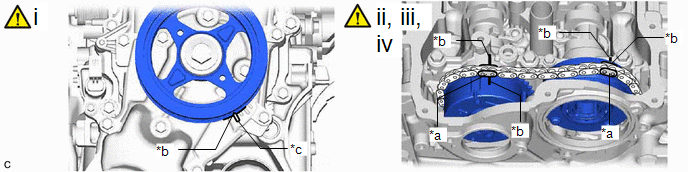
20. SET NO. 1 CYLINDER TO TDC (COMPRESSION)
|
*a | Paint Mark |
*b | Timing Mark |
|
*c | "0" Timing Mark |
- | - |
(1) Turn the crankshaft clockwise to align the timing mark (cutout) on the crankshaft pulley assembly with the "0" timing mark on the No. 2 timing chain cover assembly.
(2) Check that the timing marks are positioned as shown in the illustration.
(3) If the timing marks are not positioned as shown in the illustration, turn the crankshaft clockwise and then align them again.
(4) Place paint marks on the chain sub-assembly at points aligned with the timing marks on the camshaft timing gear assembly and camshaft timing exhaust gear assembly.
21. REMOVE STRAIGHT SCREW PLUG
Click here
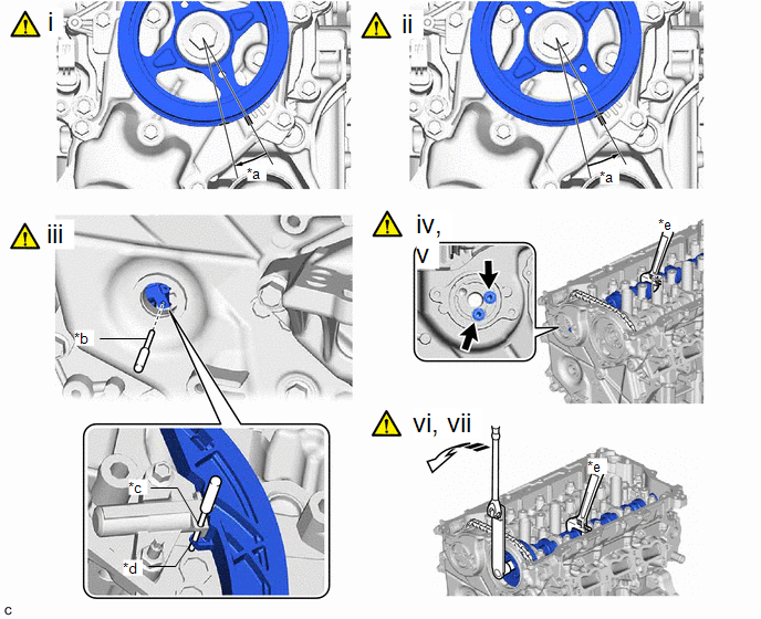
22. REMOVE CAMSHAFT TIMING GEAR
|
*a | Approximately 15° |
*b | Pin |
|
*c | Pin Hole (No. 1 Chain Tensioner Assembly Side) |
*d | Pin Hole (Chain Tensioner Slipper Side) |
|
*e | Hold |
- | - |
|
|
Turn | - |
- |
(1) Rotate the crankshaft approximately 15° clockwise.
(2) Rotate the crankshaft approximately 15° counterclockwise.
(3) Align the pin hole of the No. 1 chain tensioner assembly with the pin hole of the chain tensioner slipper, and then insert the pin.
(4) Using the hexagonal portion of the exhaust camshaft sub-assembly, secure the exhaust camshaft sub-assembly.
NOTICE:
Do not damage the camshaft housing sub-assembly, cylinder head sub-assembly and spark plug tube.
(5) Remove the 2 bolts from the camshaft timing exhaust gear assembly.
(6) Using the hexagonal portion of the intake camshaft sub-assembly, secure the intake camshaft sub-assembly.
NOTICE:
- Do not damage the camshaft housing sub-assembly, cylinder head sub-assembly and spark plug tube.
- Do not disassemble the camshaft timing gear assembly.
(7) Using a 10 mm bi-hexagon socket wrench, remove the bolt from the camshaft timing gear assembly.
|
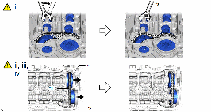
*1 | Camshaft Timing Gear Assembly |
*2 | Camshaft Timing Exhaust Gear Assembly |
|
*3 | Chain Sub-assembly |
- | - |
|
*a | Hold |
- | - |
.png) |
Turn | - |
- |
(1) Using the hexagonal portion of the exhaust camshaft sub-assembly, loosen and hold the chain sub-assembly while moving the exhaust camshaft sub-assembly in the direction shown in the illustration.
(2) Move the camshaft timing gear assembly together with the camshaft timing exhaust gear assembly and chain sub-assembly toward the No. 2 timing chain cover assembly as shown in the illustration.
(3) Remove the camshaft timing exhaust gear assembly from the chain sub-assembly.
(4) Remove the camshaft timing gear assembly from the chain sub-assembly.
23. REMOVE CAMSHAFT BEARING CAP
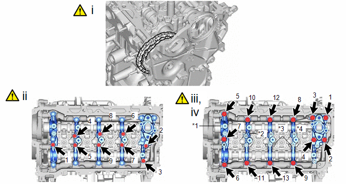
|
*1 | No. 1 Camshaft Bearing Cap |
*2 | No. 2 Camshaft Bearing Cap |
|
*3 | No. 3 Camshaft Bearing Cap |
*4 | No. 4 Camshaft Bearing Cap |
(1) Secure the chain sub-assembly to the vehicle using rope, etc.
NOTICE:
Do not drop the chain sub-assembly into the timing chain cover assembly.
(2) Uniformly loosen and remove the 9 bolts in the order shown in the illustration.
(3) Uniformly loosen and remove the 13 bolts in the order shown in the illustration.
NOTICE:
Uniformly loosen the bolts while holding the camshaft horizontally.
(4) Remove the No. 1 camshaft bearing cap, No. 2 camshaft bearing cap, 2 No. 3 camshaft bearing caps and No. 4 camshaft bearing cap.
HINT:
Arrange the removed parts so that they can be reinstalled in their original locations.
24. REMOVE INTAKE CAMSHAFT SUB-ASSEMBLY

25. REMOVE EXHAUST CAMSHAFT SUB-ASSEMBLY