Toyota Corolla Cross: ECM Power Source Circuit
DESCRIPTION
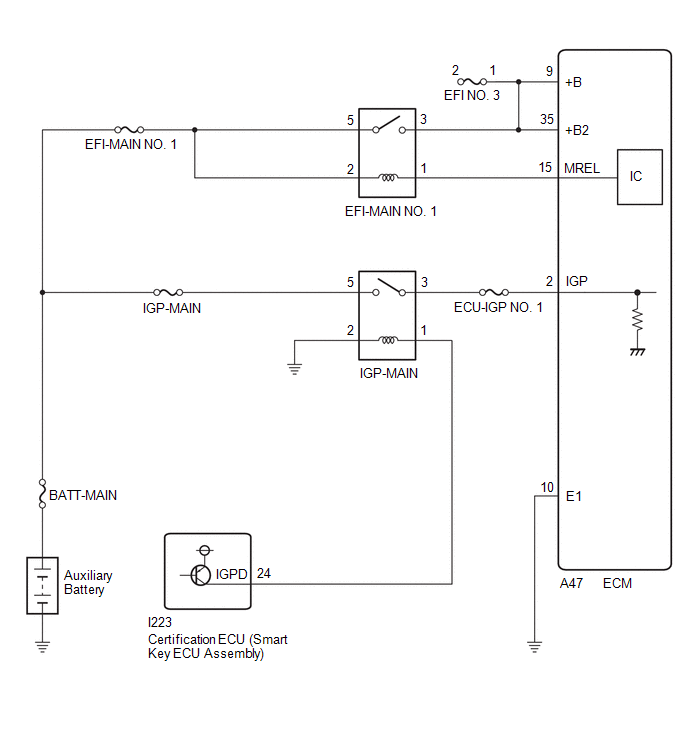
When the ignition switch is turned to ON, the auxiliary battery voltage is applied to IGP of the ECM. When the transistor in the MREL circuit operates, current flows from the auxiliary battery to ground through the drive circuit of the EFI-MAIN NO. 1 relay, thus operating the relay which supplies power to the +B and +B2 terminals of the ECM.
WIRING DIAGRAM
CAUTION / NOTICE / HINT
NOTICE:
Inspect the fuses for circuits related to this system before performing the following procedure.
PROCEDURE
| 1. |
CHECK HARNESS AND CONNECTOR (ECM - BODY GROUND) |
(a) Disconnect the ECM connector.
(b) Measure the resistance according to the value(s) in the table below.
Standard Resistance:
|
Tester Connection | Condition |
Specified Condition |
|---|---|---|
|
A47-10 (E1) - Body ground |
Always | Below 1 Ω |
| NG | .gif) | REPAIR OR REPLACE HARNESS OR CONNECTOR |
|
.gif)
| 2. |
CHECK TERMINAL VOLTAGE (IGP TERMINAL VOLTAGE) |
(a) Disconnect the ECM connector.
(b) Turn the ignition switch to ON.
(c) Measure the voltage according to the value(s) in the table below.
Standard Voltage:
|
Tester Connection | Condition |
Specified Condition |
|---|---|---|
|
A47-2 (IGP) - Body ground |
Ignition switch ON | 11 to 14 V |
| NG | | GO TO STEP 6 |
|
| 3. |
INSPECT EFI-MAIN NO. 1 RELAY |
Click here
.gif)
| NG | |
REPLACE EFI-MAIN NO. 1 RELAY |
|
| 4. |
CHECK HARNESS AND CONNECTOR (EFI-MAIN NO. 1 RELAY - ECM) |
(a) Disconnect the ECM connector.
(b) Remove the EFI-MAIN NO. 1 relay from the No. 1 engine room relay block.
(c) Measure the resistance according to the value(s) in the table below.
Standard Resistance:
|
Tester Connection | Condition |
Specified Condition |
|---|---|---|
|
3 (EFI-MAIN NO. 1 relay) - A47-9 (+B) |
Always | Below 1 Ω |
|
3 (EFI-MAIN NO. 1 relay) - A47-35 (+B2) |
Always | Below 1 Ω |
|
1 (EFI-MAIN NO. 1 relay) - A47-15 (MREL) |
Always | Below 1 Ω |
|
3 (EFI-MAIN NO. 1 relay) or A47-9 (+B) - Body ground and other terminals |
Always | 10 kΩ or higher |
|
3 (EFI-MAIN NO. 1 relay) or A47-35 (+B2) - Body ground and other terminals |
Always | 10 kΩ or higher |
|
1 (EFI-MAIN NO. 1 relay) or A47-15 (MREL) - Body ground and other terminals |
Always | 10 kΩ or higher |
HINT:
If a short is detected in any of the above circuits, there may be a malfunction in the circuit of a connected ECU.
| NG | | REPAIR OR REPLACE HARNESS OR CONNECTOR |
|
| 5. |
CHECK TERMINAL VOLTAGE (POWER SOURCE OF EFI-MAIN NO. 1 RELAY) |
(a) Remove the EFI-MAIN NO. 1 relay from the No. 1 engine room relay block.
(b) Measure the voltage according to the value(s) in the table below.
Standard Voltage:
|
Tester Connection | Condition |
Specified Condition |
|---|---|---|
|
5 (EFI-MAIN NO. 1 relay) - Body ground |
Always | 11 to 14 V |
|
2 (EFI-MAIN NO. 1 relay) - Body ground |
Always | 11 to 14 V |
| OK | | REPLACE ECM |
| NG | | REPAIR OR REPLACE HARNESS OR CONNECTOR (AUXILIARY BATTERY - EFI-MAIN NO. 1 RELAY) |
| 6. |
INSPECT IGP-MAIN RELAY |
(a) Remove the IGP-MAIN relay from the No. 1 engine room relay block.
| (b) Measure the resistance according to the value(s) in the table below. Standard Resistance:
|
|
.png)
(c) Install the IGP-MAIN relay.
| NG | |
REPLACE IGP-MAIN RELAY |
|
| 7. |
CHECK HARNESS AND CONNECTOR (IGP-MAIN RELAY - ECM) |
(a) Remove the IGP-MAIN relay from the No. 1 engine room relay block.
(b) Disconnect the ECM connector.
(c) Measure the resistance according to the value(s) in the table below.
Standard Resistance:
|
Tester Connection | Condition |
Specified Condition |
|---|---|---|
|
3 (IGP-MAIN Relay) - A47-2 (IGP-MAIN) |
Always | Below 1 Ω |
|
3 (IGP-MAIN Relay) or A47-2 (IGP-MAIN) - Body ground and other terminals |
Always | 10 kΩ or higher |
HINT:
If a short is detected in any of the above circuits, there may be a malfunction in the circuit of a connected ECU.
| NG | | REPAIR OR REPLACE HARNESS OR CONNECTOR |
|
| 8. |
CHECK TERMINAL VOLTAGE (POWER SOURCE OF IGP-MAIN RELAY) |
(a) Remove the IGP-MAIN relay from the No. 1 engine room relay block.
(b) Measure the voltage according to the value(s) in the table below.
Standard Voltage:
|
Tester Connection | Condition |
Specified Condition |
|---|---|---|
|
5 (IGP-MAIN relay) - Body ground |
Always | 11 to 14 V |
| NG | | REPAIR OR REPLACE HARNESS OR CONNECTOR (AUXILIARY BATTERY - IGP-MAIN RELAY) |
|
| 9. |
CHECK HARNESS AND CONNECTOR (IGP-MAIN RELAY - BODY GROUND) |
(a) Remove the IGP-MAIN relay from the No. 1 engine room relay block.
(b) Measure the resistance according to the value(s) in the table below.
Standard Resistance:
|
Tester Connection | Condition |
Specified Condition |
|---|---|---|
|
2 (IGP-MAIN relay) - Body ground |
Always | Below 1 Ω |
| NG | | REPAIR OR REPLACE HARNESS OR CONNECTOR |
|
| 10. |
CHECK HARNESS AND CONNECTOR (CERTIFICATION ECU (SMART KEY ECU ASSEMBLY) - IGP-MAIN RELAY) |
(a) Disconnect the certification ECU (smart key ECU assembly) connector.
(b) Remove the IGP-MAIN relay from the No. 1 engine room relay block.
(c) Measure the resistance according to the value(s) in the table below.
Standard Resistance:
|
Tester Connection | Condition |
Specified Condition |
|---|---|---|
|
I223-24 (IGPD) - 2 (IGP-MAIN relay) |
Always | Below 1 Ω |
|
I223-24 (IGPD) or 2 (IGP-MAIN relay) - Body ground and other terminals |
Always | 10 kΩ or higher |
| OK | | GO TO SMART KEY SYSTEM (FOR START FUNCTION) |
| NG | | REPAIR OR REPLACE HARNESS OR CONNECTOR |


