Toyota Corolla Cross: Disassembly
DISASSEMBLY
CAUTION / NOTICE / HINT
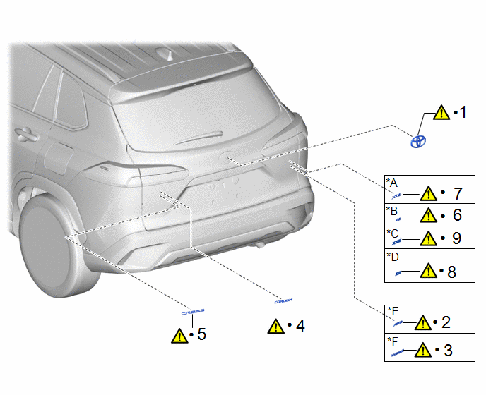
COMPONENTS (DISASSEMBLY)
|
Procedure | Part Name Code |
.png) |
.png) |
 |
|---|---|---|---|---|---|
|
1 | SYMBOL EMBLEM |
75741E |
|
- | - |
|
2 | NO. 4 LUGGAGE COMPARTMENT DOOR NAME PLATE |
75444C |
|
- | - |
|
3 | BACK DOOR NAME PLATE |
75444C |
|
- | - |
|
4 | NO. 2 BACK DOOR NAME PLATE |
75442A |
|
- | - |
|
5 | NO. 5 BACK DOOR NAME PLATE |
75445A |
|
- | - |
|
6 | NO. 4 BACK DOOR NAME PLATE |
75444A |
|
- | - |
|
7 | NO. 4 BACK DOOR NAME PLATE |
75444A |
|
- | - |
|
8 | NO. 4 BACK DOOR NAME PLATE |
75444A |
|
- | - |
|
9 | NO. 4 BACK DOOR NAME PLATE |
75444A |
|
- | - |
|
*A | for AWD |
*B | for HV Model |
|
*C | for Type A |
*D | for Type B |
|
*E | for Type C |
*F | for Type D |
|
● | Non-reusable part |
- | - |

|
Procedure | Part Name Code |
.png) |
.png) |
 |
|---|---|---|---|---|---|
|
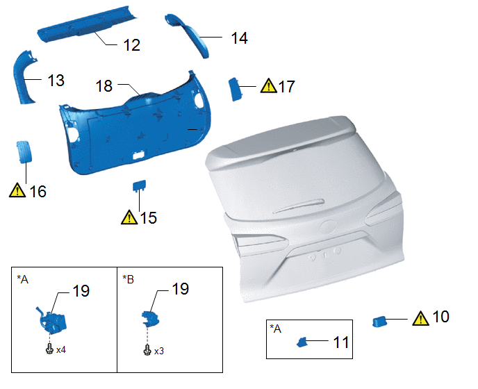
10 | DOOR PULL HANDLE |
74811B |
|
- | - |
|
11 | BACK DOOR INSIDE HANDLE BASE ASSEMBLY |
69290G | - |
- | - |
|
12 | BACK DOOR TRIM UPPER PANEL ASSEMBLY |
64790B | - |
- | - |
|
13 | BACK DOOR SIDE GARNISH LH |
67938A | - |
- | - |
|
14 | BACK DOOR SIDE GARNISH RH |
67937B | - |
- | - |
|
15 | NO. 3 BACK DOOR SERVICE HOLE COVER |
67767B |
|
- | - |
|
16 | BACK DOOR SERVICE HOLE COVER LH |
67848 |
|
- | - |
|
17 | BACK DOOR SERVICE HOLE COVER RH |
67847E |
|
- | - |
|
18 | BACK DOOR TRIM PANEL ASSEMBLY |
64780A | - |
- | - |
|
19 | BACK DOOR LOCK WITH COURTESY LIGHT SWITCH ASSEMBLY |
69350P | - |
- | - |
|
*A | w/ Power Back Door |
*B | w/o Power Back Door |

|
Procedure | Part Name Code |
.png) |
.png) |
 |
|---|---|---|---|---|---|
|
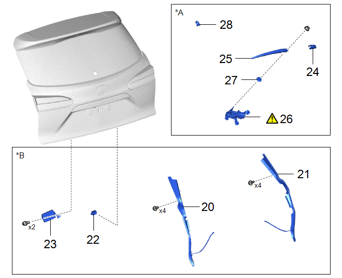
20 | POWER BACK DOOR SENSOR ASSEMBLY LH |
84280D | - |
- | - |
|
21 | POWER BACK DOOR SENSOR ASSEMBLY RH |
84270G | - |
- | - |
|
22 | POWER BACK DOOR WARNING BUZZER |
89747E | - |
- | - |
|
23 | MULTIPLEX NETWORK DOOR ECU |
89222A | - |
- | - |
|
24 | REAR WIPER ARM HEAD CAP |
85292A | - |
- | - |
|
25 | REAR WIPER ARM AND BLADE ASSEMBLY |
- | - |
- | - |
|
26 | REAR WIPER MOTOR ASSEMBLY |
85110R |
|
- | - |
|
27 | REAR WIPER MOTOR GROMMET |
85143R | - |
- | - |
|
28 | REAR WASHER NOZZLE |
85345R | - |
- | - |
|
*A | w/ Rear Wiper |
*B | w/ Power Back Door |

|
Procedure | Part Name Code |
.png) |
.png) |
 |
|---|---|---|---|---|---|
|
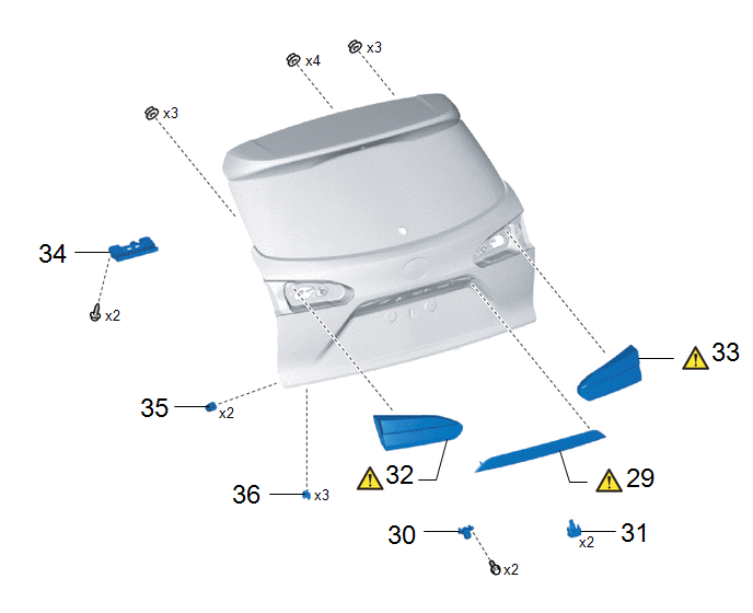
29 | BACK DOOR OUTSIDE GARNISH |
76811 |
|
- | - |
|
30 | REAR TELEVISION CAMERA ASSEMBLY |
86790D | - |
- | - |
|
31 | LICENSE PLATE LIGHT ASSEMBLY |
81270 | - |
- | - |
|
32 | REAR LIGHT ASSEMBLY LH |
81590A |
|
- | - |
|
33 | REAR LIGHT ASSEMBLY RH |
81580D |
|
- | - |
|
34 | CENTER STOP LIGHT ASSEMBLY |
81570 | - |
- | - |
|
35 | BACK DOOR PANEL CUSHION |
67005B | - |
- | - |
|
36 | BACK DOOR DUST PROOF SEAL |
67837N | - |
- | - |
CAUTION / NOTICE / HINT
The necessary procedures (adjustment, calibration, initialization, or registration) that must be performed after parts are removed and installed, or replaced during the back door removal/installation are shown below.
Necessary Procedures After Parts Removed/Installed/Replaced|
Replaced Part or Performed Procedure |
Necessary Procedures | Effect/Inoperative Function when Necessary Procedure not Performed |
Link |
|---|---|---|---|
| Rear television camera assembly |
| Parking assist monitor system |
|
|
Multiplex network door ECU |
Initialize power back door system |
Power Back Door System |
|
PROCEDURE
1. REMOVE SYMBOL EMBLEM
.png) |
Click here |
2. REMOVE NO. 4 LUGGAGE COMPARTMENT DOOR NAME PLATE (for AWD)
.png) |
Click here |
3. REMOVE LUGGAGE COMPARTMENT DOOR NAME PLATE NO.4 (for HV Model)
.png) |
Click here |
4. REMOVE NO. 2 BACK DOOR NAME PLATE
.png) |
Click here |
5. REMOVE NO. 5 BACK DOOR NAME PLATE
.png) |
Click here |
6. REMOVE NO. 4 BACK DOOR NAME PLATE (for Type A)
.png) |
Click here |
7. REMOVE NO. 4 BACK DOOR NAME PLATE (for Type B)
.png) |
Click here |
8. REMOVE NO. 4 BACK DOOR NAME PLATE (for Type C)
.png) |
Click here |
9. REMOVE NO. 4 BACK DOOR NAME PLATE (for Type D)
.png) |
Click here |
10. REMOVE DOOR PULL HANDLE

(1) Using a moulding remover D, disengage the claws to remove the door pull handle.
11. REMOVE BACK DOOR INSIDE HANDLE BASE ASSEMBLY (w/ Power Back Door)

12. REMOVE BACK DOOR TRIM UPPER PANEL ASSEMBLY

13. REMOVE BACK DOOR SIDE GARNISH LH

14. REMOVE BACK DOOR SIDE GARNISH RH
(a) Use the same procedure as for the LH side.
15. REMOVE NO. 3 BACK DOOR SERVICE HOLE COVER

(1) Using a moulding remover A, disengage the claws and guides to remove the No. 3 back door service hole cover.
16. REMOVE BACK DOOR SERVICE HOLE COVER LH

(1) Using a moulding remover A, disengage the claws and guides to remove the back door service hole cover LH.
17. REMOVE BACK DOOR SERVICE HOLE COVER RH
(a) Use the same procedure as for the LH side.
18. REMOVE BACK DOOR TRIM PANEL ASSEMBLY

19. REMOVE BACK DOOR LOCK WITH COURTESY LIGHT SWITCH ASSEMBLY
Click here .gif)
20. REMOVE POWER BACK DOOR SENSOR ASSEMBLY LH (w/ Power Back Door)
Click here .gif)
21. REMOVE POWER BACK DOOR SENSOR ASSEMBLY RH (w/ Power Back Door)
(a) Use the same procedure as for the LH side.
22. REMOVE POWER BACK DOOR WARNING BUZZER (w/ Power Back Door)
Click here .gif)
23. REMOVE MULTIPLEX NETWORK DOOR ECU (w/ Power Back Door)
Click here .gif)
24. REMOVE REAR WIPER ARM HEAD CAP (w/ Rear Wiper)
Click here .gif)
25. REMOVE REAR WIPER ARM AND BLADE ASSEMBLY (w/ Rear Wiper)
Click here .gif)
26. REMOVE REAR WIPER MOTOR ASSEMBLY (w/ Rear Wiper)
.png) |
Click here |
27. REMOVE REAR WIPER MOTOR GROMMET (w/ Rear Wiper)
Click here
.gif)
28. REMOVE REAR WASHER NOZZLE (w/ Rear Wiper)
Click here .gif)
29. REMOVE BACK DOOR OUTSIDE GARNISH
.png) |
Click here |
30. REMOVE REAR TELEVISION CAMERA ASSEMBLY
Click here
.gif)
31. REMOVE LICENSE PLATE LIGHT ASSEMBLY
Click here .gif)
32. REMOVE REAR LIGHT ASSEMBLY LH
.png) |
Click here |
33. REMOVE REAR LIGHT ASSEMBLY RH
(a) Use the same procedure as for the LH side.
34. REMOVE CENTER STOP LIGHT ASSEMBLY
Click here
.gif)
35. REMOVE BACK DOOR PANEL CUSHION

36. REMOVE BACK DOOR DUST PROOF SEAL


