Toyota Corolla Cross Owners & Service Manuals

Toyota Corolla Cross: Disassembly

DISASSEMBLY

CAUTION / NOTICE / HINT

COMPONENTS (DISASSEMBLY)
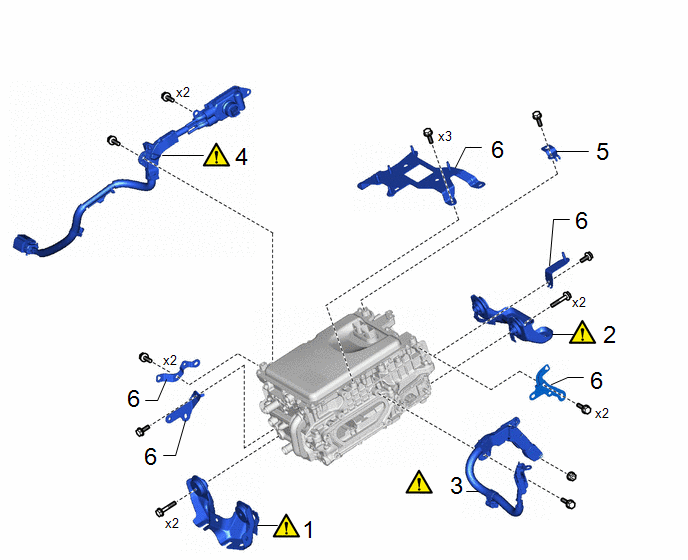
Procedure

Part Name Code

1

NO. 1 INVERTER BRACKET

G9214

-

-

2

NO. 2 INVERTER BRACKET

G9215

-

-

3

NO. 3 ENGINE WIRE

82123

-

-

4

HV AIR CONDITIONING WIRE

821H2

-

-

5

FUEL HOSE BRACKET

23881B

-

-

-

6

WIRE HARNESS CLAMP BRACKET

-

-

-

-

PROCEDURE

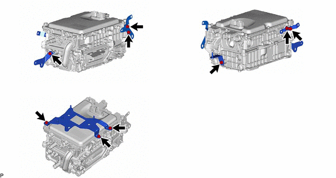
1. REMOVE NO. 1 INVERTER BRACKET

NOTICE:

Make sure to support the inverter with converter assembly at the positions shown in the illustration, otherwise it may be damaged.

  • *a: Bottom of Inverter with Converter Assembly

    *b: Support

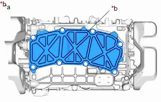
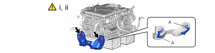
(1) Set the inverter with converter assembly on wooden blocks.

(2) Remove the 2 bolts and No. 1 inverter bracket from the inverter with converter assembly.

NOTICE:

Do not touch portion (A) of the No. 1 inverter bracket.

2. REMOVE NO. 2 INVERTER BRACKET

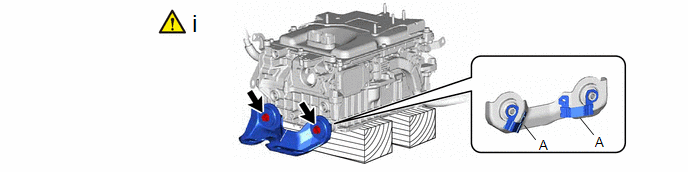
(1) Remove the 2 bolts and No. 2 inverter bracket from the inverter with converter assembly.

NOTICE:

Do not touch portion (A) of the No. 2 inverter bracket.

3. REMOVE NO. 3 ENGINE WIRE

CAUTION:

Be sure to wear insulated gloves.

NOTICE:

  • Do not allow any foreign matter or water to enter the inverter with converter assembly.
  • Perform this procedure when it is necessary to replace the inverter with converter assembly or the No. 3 engine wire.

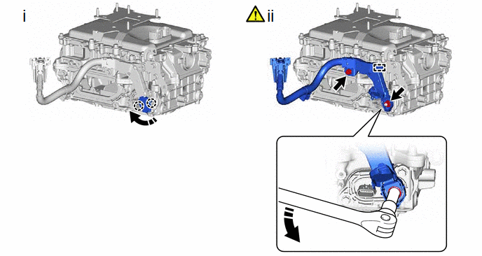
(1) Disengage the 2 claws and open the cover.

(2) Remove the bolt, nut, clamp and disconnect the no. 3 engine wire from the inverter with converter assembly.

NOTICE:

Move the tool in the downward direction to loosen the nut as shown in the illustration.

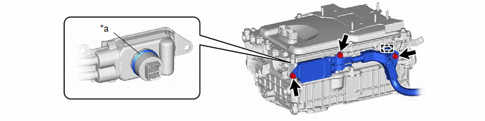
4. REMOVE HV AIR CONDITIONING WIRE

CAUTION:

Be sure to wear insulated gloves.

NOTICE:

  • Do not touch the waterproof seal or terminals of the connector.
  • Do not damage the terminals, connector housing or inverter with converter assembly during disconnection.
  • Cover the hole where the cable was connected with tape (non-residue type) or equivalent to prevent entry of foreign matter.
  • Do not allow any foreign matter or water to enter the inverter with converter assembly.
  • Insulate the disconnected terminals with insulating tape.

*a

Waterproof Seal

-

-

5. REMOVE FUEL HOSE BRACKET

6. REMOVE WIRE HARNESS CLAMP BRACKET

    READ NEXT:

     Reassembly

    REASSEMBLY CAUTION / NOTICE / HINT Procedure Part Name Code 1 WIRE HARNESS CLAMP BRACKET - - - - 2 FUEL HOSE BRACKET 23

     Installation

    INSTALLATION CAUTION / NOTICE / HINT COMPONENTS (INSTALLATION) Procedure Part Name Code 1 SET INVERTER WITH CONVERTER ASSEMBLY G92A0

     Motor Generator Control System

    SEE MORE:

     Evaporative Emission System Pressure Sensor/Switch Circuit Short to Ground (P045011,P045015,P04502F)

    DTC SUMMARY DTC No. Detection Item DTC Detection Condition Trouble Area MIL Note P045011 Evaporative Emission System Pressure Sensor/Switch Circuit Short to Ground EVAP pressure is less than 42.110 kPa(abs) [6.106 psi(abs)] for 0.5 seconds or more. Ca

     Removal

    REMOVAL CAUTION / NOTICE / HINT COMPONENTS (REMOVAL) Procedure Part Name Code 1 UPPER BACK DOOR TRIM PANEL ASSEMBLY 64790B - - - 2 BACK DOOR SIDE GARNISH LH 67938A - - - 3 BACK DOOR SIDE GARNISH RH 67937B - -

    © 2020-2025 Copyright www.tcorollacross.com