Toyota Corolla Cross: Installation
INSTALLATION
CAUTION / NOTICE / HINT
COMPONENTS (INSTALLATION)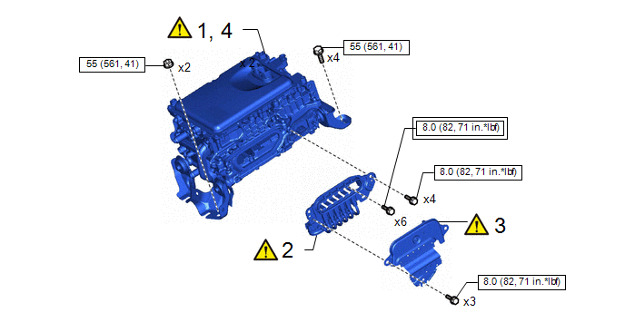
|
Procedure | Part Name Code |
.png) |
.png) |
 |
|---|---|---|---|---|---|
|
1 | SET INVERTER WITH CONVERTER ASSEMBLY |
G92A0 |
|
- | - |
|
2 | MOTOR CABLE |
G1148 |
|
- | - |
|
3 | UPPER INVERTER COVER |
G9221 |
|
- | - |
|
4 | INSTALL INVERTER WITH CONVERTER ASSEMBLY |
G92A0 |
|
- | - |
.png) |
Tightening torque for "Major areas involving basic vehicle performance such as moving/turning/stopping" : N*m (kgf*cm, ft.*lbf) |
.png) |
N*m (kgf*cm, ft.*lbf): Specified torque |
|
Procedure | Part Name Code |
|
|
| |
|---|---|---|---|---|---|
|
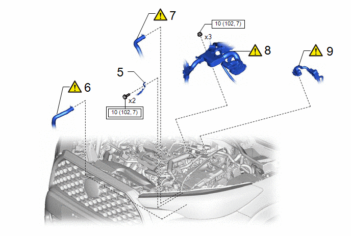
5 | NO. 7 ENGINE, WIRE |
82127D | - |
- | - |
|
6 | INLET NO. 1 INVERTER COOLING HOSE |
G922AA |
|
- | - |
|
7 | OUTLET NO. 1 INVERTER COOLING HOSE |
G922C |
|
- | - |
|
8 | ENGINE WIRE |
82121 |
|
- | - |
|
9 | ENGINE ROOM MAIN WIRE |
82111 |
|
- | - |
|
|
Tightening torque for "Major areas involving basic vehicle performance such as moving/turning/stopping" : N*m (kgf*cm, ft.*lbf) |
|
N*m (kgf*cm, ft.*lbf): Specified torque |
|
Procedure | Part Name Code |
|
|
| |
|---|---|---|---|---|---|
|
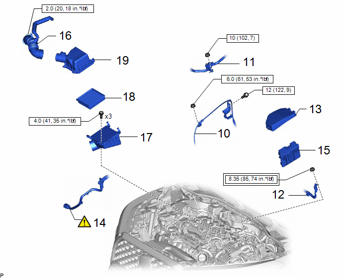
10 | TRANSMISSION CONTROL CABLE ASSEMBLY |
33820B | - |
- | - |
|
11 | VACUUM SWITCHING VALVE ASSEMBLY |
17650 | - |
- | - |
|
12 | NO.3 ENGINE WIRE |
82123 | - |
- | - |
|
13 | NO.2 RELAY BLOCK COVER |
82662B | - |
- | - |
|
14 | HV AIR CONDITIONING WIRE |
821H2 |
|
- | - |
|
15 | ECM |
89661 | - |
- | - |
|
16 | NO. 1 AIR CLEANER HOSE |
17881 | - |
- | - |
|
17 | AIR CLEANER CASE SUB-ASSEMBLY |
17701 | - |
- | - |
|
18 | AIR CLEANER FILTER ELEMENT SUB-ASSEMBLY |
17801 | - |
- | - |
|
19 | AIR CLEANER CAP SUB-ASSEMBLY |
17705 | - |
- | - |
|
|
Tightening torque for "Major areas involving basic vehicle performance such as moving/turning/stopping" : N*m (kgf*cm, ft.*lbf) |
|
N*m (kgf*cm, ft.*lbf): Specified torque |
|
Procedure | Part Name Code |
|
|
| |
|---|---|---|---|---|---|
|
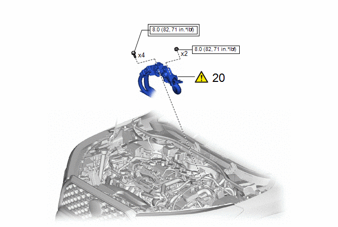
20 | FLOOR UNDER WIRE |
821H1 |
|
- | - |
|
|
Tightening torque for "Major areas involving basic vehicle performance such as moving/turning/stopping" : N*m (kgf*cm, ft.*lbf) |
|
N*m (kgf*cm, ft.*lbf): Specified torque |

|
Procedure | Part Name Code |
|
|
| |
|---|---|---|---|---|---|
|
21 | SERVICE PLUG GRIP |
G3834 | - |
- | - |
|
22 | COOLANT (for Inverter) |
- | - |
|
- |
| 23 |
FOR COOLANT LEAK |
- |
|
- | - |
|
24 | ECU CONFIGURATION |
- | - |
- |
|
|
25 | RESOLVER LEARNING |
- | - |
- |
|
PROCEDURE
1. SET INVERTER WITH CONVERTER ASSEMBLY
|
|
CAUTION: Be sure to wear insulated gloves. NOTICE:
|
.png)
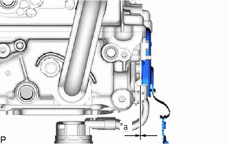
2. CONNECT MOTOR CABLE
|
|
CAUTION: Wear insulated gloves. NOTICE: Do not allow any foreign matter or water to enter the hybrid motor control inverter assembly. |
|
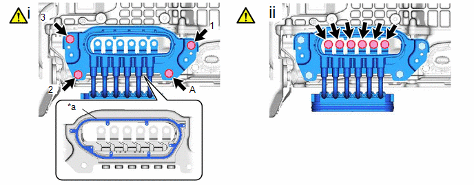
*a | Waterproof Seal |
- | - |
(1) Temporarily install the motor cable to the inverter with converter assembly with the 4 bolts,
NOTICE:
- Do not touch the waterproof seal or terminals of the motor cable.
- Do not damage the terminals, connector housing or inverter with converter assembly during connection.
- Be careful to avoid cutting or pinching the waterproof seal during installation.
(2) Fully tighten the 3 bolts in the order shown in the illustration.
Torque:
8.0 N·m {82 kgf·cm}
(3) Using a 10 mm union nut wrench, fully tighten the bolt(A).
Torque:
Specified Tightening Torque :
8.0 N·m {82 kgf·cm, 71 in·lbf}
HINT:
- Calculate the torque wrench reading when changing the fulcrum length of the torque wrench.
Click here
.gif)
- When using a union nut wrench (fulcrum length of 22 mm (0.866 in.)) + torque wrench (fulcrum length of 162 mm (6.38 in.)): 7.0 N*m (71 kgf*cm, 62 in.*lbf)
(4) Temporarily install the terminals of the motor cable with the bolts, and using an insulated tool, fully tighten the bolts.
Torque:
8.0 N·m {82 kgf·cm}
NOTICE:
- To prevent the threads from being damaged, temporarily tighten the 6 bolts by hand.
- Be sure to use a torque wrench to tighten the bolts.
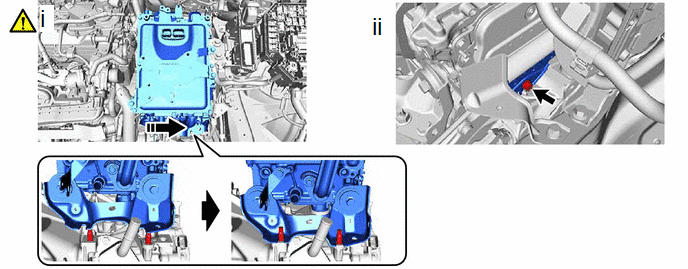
3. INSTALL UPPER INVERTER COVER
|
|
CAUTION: Wear insulated gloves. |
|
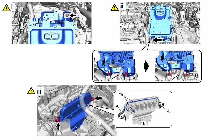
*a | Interlock |
*b | Waterproof Seal |
(1) To prevent the inverter with converter assembly from falling, temporarily install the bolt in the location shown in the illustration.
(2) Shift the position of the inverter with converter assembly and temporarily set it on top of the stud bolts as shown in the illustration.
NOTICE:
When lifting, make sure not to apply force to the motor cable.
(3) Install the inverter cover to the inverter with converter assembly with the bolts.
Torque:
8.0 N·m {82 kgf·cm}
NOTICE:
- Visually confirm that the inverter cover waterproof seal is securely installed before installing the upper inverter cover.
- Do not touch the waterproof seal of the upper inverter cover.
- Make sure that the interlock is fully engaged.
- Do not damage the terminals, interlock connector or hybrid motor control inverter assembly during installation.
- Do not allow any foreign matter or water to enter the hybrid motor control inverter assembly.
- Do not remove or excessively tighten the screw of the upper inverter cover.
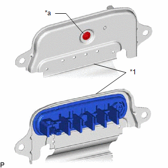
*1
Inverter Cover
*a
Screw
- Although the upper inverter cover may feel loose, this is not due to a malfunction.
- Push in the upper inverter cover until it contacts the hybrid motor control inverter assembly.
*a
No Gap
(1) Shift the position of the inverter with converter assembly and temporarily set it on the hybrid vehicle transaxle assembly as shown in the illustration.
NOTICE:
When lifting, make sure not to apply force to the motor cable.
(2) Connect the inverter cover to the hybrid vehicle transaxle assembly with the bolt.
Torque:
8.0 N·m {82 kgf·cm}
4. INSTALL HYBRID MOTOR CONTROL INVERTER ASSEMBLY
|
|
CAUTION: Wear insulated gloves. |

(1) Temporarily install the inverter with converter assembly with the bolts and the nuts, and then fully tighten the bolts and nuts in the order shown in the illustration.
Torque:
55 N·m {561 kgf·cm}
NOTICE:
- When installing the inverter with converter assembly, be careful not to damage the parts around it.
- To prevent damage due to static electricity, do not touch the terminals of the disconnected connectors.
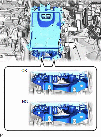
- Make sure that the inverter with converter assembly is positioned so that the stud bolts are in contact with the base of the U-shaped portions of the No. 1 inverter bracket.
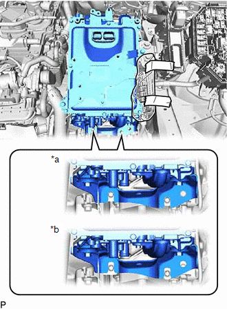
*a
Correct
*b
Incorrect
HINT:
If the bolts and nuts are not tightened appropriately, the inverter with converter assembly may make an abnormal noise.
5. INSTALL NO. 7 ENGINE WIRE
Torque:
10 N·m {102 kgf·cm, 7 ft·lbf}
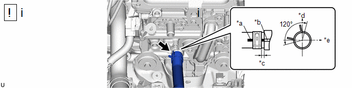
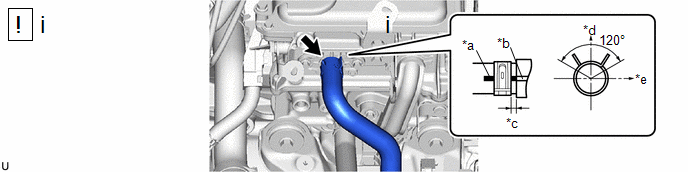
6. CONNECT INLET NO. 1 INVERTER COOLING HOSE
|
*a | Alignment Mark |
*b | Rib |
|
*c | 2 to 7 mm (0.0787 to 0.2756 in.) |
*d | Up |
|
*e | LH Side |
- | - |
(1) Connect the inlet No. 1 inverter cooling hose to the hybrid motor control inverter assembly and slide the clip to secure it.
NOTICE:
To prevent foreign matter from entering the hybrid motor control inverter assembly and inverter cooling system, do not remove the pieces of cloth from the pipe and disconnected hose until installation.
7. CONNECT OUTLET NO. 1 INVERTER COOLING HOSE
|
*a | Alignment Mark |
*b | Rib |
|
*c | 2 to 7 mm (0.0787 to 0.2756 in.) |
*d | Up |
|
*e | LH Side |
- | - |
(1) Connect the outlet No. 1 inverter cooling hose to the hybrid motor control inverter assembly and slide the clip to secure it.
NOTICE:
To prevent foreign matter from entering the hybrid motor control inverter assembly and inverter cooling system, do not remove the pieces of cloth from the pipe and disconnected hose until installation.
8. INSTALL ENGINE WIRE
|
|
CAUTION: Wear insulated gloves. NOTICE:
|
Torque:
10 N·m {102 kgf·cm, 89 in·lbf}
9. INSTALL ENGINE ROOM MAIN WIRE
10. INSTALL TRANSMISSION CONTROL CABLE ASSEMBLY
Torque:
Nut :
6.0 N·m {61 kgf·cm, 53 in·lbf}
Bolt :
12 N·m {122 kgf·cm, 9 ft·lbf}
11. INSTALL PURGE VALVE (PURGE VSV)
Torque:
10 N·m {102 kgf·cm, 7 ft·lbf}
12. INSTALL NO. 3 ENGINE WIRE
Torque:
8.35 N·m {85 kgf·cm, 74 in·lbf}
13. INSTALL NO. 2 RELAY BLOCK COVER
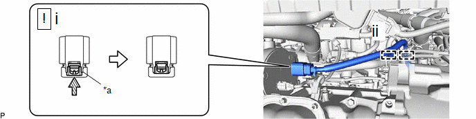
14. CONNECT HV AIR CONDITIONING WIRE
|
|
CAUTION: Wear insulated gloves. NOTICE:
|
|
*a | Green-colored Lock |
- | - |
 |
Slide | - |
- |
(1) Connect the connector and slide the green-colored lock as shown in the illustration to securely lock it.
(2) Engage the 2 clamps.
15. INSTALL ECM
Click here
16. INSTALL NO. 1 AIR CLEANER HOSE
Torque:
2.0 N·m {20 kgf·cm, 18 in·lbf}
17. INSTALL AIR CLEANER CASE SUB-ASSEMBLY
Torque:
4.0 N·m {41 kgf·cm, 35 in·lbf}
18. INSTALL AIR CLEANER FILTER ELEMENT SUB-ASSEMBLY
19. INSTALL AIR CLEANER CAP SUB-ASSEMBLY
20. CONNECT FLOOR UNDER WIRE
|
|
CAUTION: Wear insulated gloves. NOTICE:
|
Torque:
8.0 N·m {82 kgf·cm, 71 in·lbf}
21. INSTALL SERVICE PLUG GRIP
Click here
22. ADD COOLANT (for Inverter)
Click here
23. INSPECT FOR COOLANT LEAK (for Inverter)
Click here
24. PEFOME ECU CONFIGURATION
Click here
25. PERFORM RESOLVER LEARNING
Click here


