Toyota Corolla Cross: Crankshaft Position Sensor "A" Circuit Short to Battery or Open (P033515)
DESCRIPTION
Refer to DTC P033511.
Click here
.gif)
|
DTC No. | Detection Item |
DTC Detection Condition | Trouble Area |
MIL | Note |
|---|---|---|---|---|---|
|
P033515 | Crankshaft Position Sensor "A" Circuit Short to Battery or Open |
Diagnosis condition:
Abnormal condition:
Malfunction time:
Trip logic:
Detection conditions:
Sensors/components used for detection (Main):
Sensors/components used for detection (Related):
|
| Comes on |
|
- Reference: Inspection using an oscilloscope.
Click here
MONITOR DESCRIPTION
When the ignition switch is turned ON and the output voltage of the crankshaft position sensor is higher than 4.7 V for 4 seconds or more, the ECM determines that the crankshaft position sensor circuit is malfunctioning and illuminates the MIL and stores a DTC.
MONITOR STRATEGY
|
Related DTCs | P0338: Crankshaft position sensor range check (High voltage) |
|
Required Sensors/Components (Main) | Crankshaft position sensor |
|
Required Sensors/Components (Related) |
Camshaft position sensor |
|
Frequency of Operation | Continuous |
|
Duration | 4 seconds |
|
MIL Operation | Immediate |
|
Sequence of Operation | None |
TYPICAL ENABLING CONDITIONS
|
Monitor runs whenever following DTCs are not present |
None |
| All of the following conditions are met |
- |
| Auxiliary battery voltage |
8 V or higher |
| Ignition switch |
ON |
| Starter |
Off |
TYPICAL MALFUNCTION THRESHOLDS
|
Crankshaft position sensor voltage | Higher than 4.7 V |
CONFIRMATION DRIVING PATTERN
Refer to DTC P033511.
Click here
WIRING DIAGRAM
Refer to DTC P033511.
Click here
CAUTION / NOTICE / HINT
HINT:
- The engine speed can be checked by using the GTS. To perform the check, follow the procedures below:
- Connect the GTS to the DLC3.
- Turn the ignition switch to ON.
- Turn the GTS on.
- Enter the following menus: Powertrain / Engine / Data List / Engine Speed.
- Start the engine.
- The engine speed may be indicated as zero despite the engine running normally. This is caused by a lack of NE signals from the crankshaft position sensor. Alternatively, the engine speed may be indicated as lower than the actual engine speed if the crankshaft position sensor output voltage is insufficient.
- Read Freeze Frame Data using the GTS. The ECM records vehicle and driving condition information as Freeze Frame Data the moment a DTC is stored. When troubleshooting, Freeze Frame Data can help determine if the vehicle was moving or stationary, if the engine was warmed up or not, if the air fuel ratio was lean or rich, and other data from the time the malfunction occurred.
PROCEDURE
|
1. | CHECK TERMINAL VOLTAGE (CRANKSHAFT POSITION SENSOR) |
|
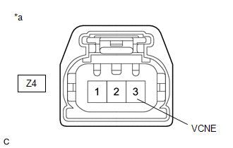
*a | Front view of wire harness connector (to Crankshaft Position Sensor) |
HINT:
Make sure that the connector is properly connected. If it is not, securely connect it and check for DTCs again.
(a) Disconnect the crankshaft position sensor connector.
(b) Turn the ignition switch to ON.
(c) Measure the voltage according to the value(s) in the table below.
Standard Voltage:
|
Tester Connection | Condition |
Specified Condition |
|---|---|---|
|
Z4-3 (VCNE) - Body ground |
Ignition switch ON | 4.5 to 5.5 V |
|
Result | Proceed to |
|---|---|
|
Higher than 5.5 V | A |
|
4.5 to 5.5 V | B |
|
Below 4.5 V | C |
| B |
.gif) | GO TO STEP 3 |
| C |
| GO TO STEP 10 |
|
.gif)
| 2. |
CHECK HARNESS AND CONNECTOR (CRANKSHAFT POSITION SENSOR - ECM) |
(a) Disconnect the crankshaft position sensor connector.
(b) Disconnect the ECM connector.
(c) Measure the resistance according to the value(s) in the table below.
Standard Resistance:
|
Tester Connection | Condition |
Specified Condition |
|---|---|---|
|
Z4-3 (VCNE) or C76-116(VCNE) - Other terminals |
Always | 10 kΩ or higher |
| OK | | REPLACE ECM
|
| NG | | REPAIR OR REPLACE HARNESS OR CONNECTOR |
| 3. |
CHECK TERMINAL VOLTAGE (CRANKSHAFT POSITION SENSOR) |
|
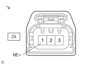
*a | Front view of wire harness connector (to Crankshaft Position Sensor) |
(a) Disconnect the crankshaft position sensor connector.
(b) Turn the ignition switch to ON.
(c) Measure the voltage according to the value(s) in the table below.
Standard Voltage:
|
Tester Connection | Condition |
Specified Condition |
|---|---|---|
|
Z4-1 (NE+) - Body ground |
Ignition switch ON | 3.0 to 5.0 V |
|
Result | Proceed to |
|---|---|
|
Higher than 5.0 V | A |
|
3.0 to 5.0 V | B |
|
Below 3.0 V | C |
| B |
| GO TO STEP 5 |
| C |
| GO TO STEP 9 |
|
| 4. |
CHECK HARNESS AND CONNECTOR (CRANKSHAFT POSITION SENSOR - ECM) |
(a) Disconnect the crankshaft position sensor connector.
(b) Disconnect the ECM connector.
(c) Measure the resistance according to the value(s) in the table below.
Standard Resistance:
|
Tester Connection | Condition |
Specified Condition |
|---|---|---|
|
Z4-1 (NE+) or C76-93(NE+) - Other terminals |
Always | 10 kΩ or higher |
| OK | | REPLACE ECM
|
| NG | | REPAIR OR REPLACE HARNESS OR CONNECTOR |
| 5. |
CHECK HARNESS AND CONNECTOR (CRANKSHAFT POSITION SENSOR - BODY GROUND) |
(a) Disconnect the crankshaft position sensor connector.
(b) Measure the resistance according to the value(s) in the table below.
Standard Resistance:
|
Tester Connection | Condition |
Specified Condition |
|---|---|---|
|
Z4-2 (NE-) - Body ground |
Always | Below 1 Ω |
| NG | | GO TO STEP 8 |
|
| 6. |
CHECK INTERNAL RESISTANCE (ECM) |
(a) Turn the ignition switch off.
(b) Disconnect the crankshaft position sensor connector.
(c) Measure the resistance according to the value(s) in the table below.
Standard Resistance:
|
Tester Connection | Condition |
Specified Condition |
|---|---|---|
|
Z4-3 (VCNE) - Z4-1 (NE+) |
Ignition switch off | 1.425 to 1.575 kΩ |
HINT:
As voltage is still supplied to the ECM after the ignition switch is turned off, this check cannot be performed correctly during the shut-down process.
| OK | | REPLACE CRANKSHAFT POSITION SENSOR
|
|
| 7. |
CHECK HARNESS AND CONNECTOR (CRANKSHAFT POSITION SENSOR - ECM) |
(a) Disconnect the crankshaft position sensor connector.
(b) Disconnect the ECM connector.
(c) Measure the resistance according to the value(s) in the table below.
Standard Resistance:
|
Tester Connection | Condition |
Specified Condition |
|---|---|---|
|
Z4-3 (VCNE) - Z4-1 (NE+) or C76-116 (VCNE) - C76-93 (NE+) |
Always | 10 kΩ or higher |
| OK | | REPLACE ECM
|
| NG | | REPAIR OR REPLACE HARNESS OR CONNECTOR |
| 8. |
CHECK HARNESS AND CONNECTOR (CRANKSHAFT POSITION SENSOR - ECM) |
(a) Disconnect the crankshaft position sensor connector.
(b) Disconnect the ECM connector.
(c) Measure the resistance according to the value(s) in the table below.
Standard Resistance:
|
Tester Connection | Condition |
Specified Condition |
|---|---|---|
|
Z4-2 (NE-) - C76-115 (NE-) |
Always | Below 1 Ω |
| OK | | REPLACE ECM
|
| NG | | REPAIR OR REPLACE HARNESS OR CONNECTOR |
| 9. |
CHECK HARNESS AND CONNECTOR (CRANKSHAFT POSITION SENSOR - ECM) |
(a) Disconnect the crankshaft position sensor connector.
(b) Disconnect the ECM connector.
(c) Measure the resistance according to the value(s) in the table below.
Standard Resistance:
|
Tester Connection | Condition |
Specified Condition |
|---|---|---|
|
Z4-1 (NE+) - C76-93 (NE+) |
Always | Below 1 Ω |
| OK | | REPLACE ECM
|
| NG | | REPAIR OR REPLACE HARNESS OR CONNECTOR |
| 10. |
CHECK HARNESS AND CONNECTOR (CRANKSHAFT POSITION SENSOR - ECM) |
(a) Disconnect the crankshaft position sensor connector.
(b) Disconnect the ECM connector.
(c) Measure the resistance according to the value(s) in the table below.
Standard Resistance:
|
Tester Connection | Condition |
Specified Condition |
|---|---|---|
|
Z4-3 (VCNE) - C76-116 (VCNE) |
Always | Below 1 Ω |
| OK | | REPLACE ECM
|
| NG | | REPAIR OR REPLACE HARNESS OR CONNECTOR |
READ NEXT:
 Crankshaft Position Sensor "A" Circuit Intermittent (P03351F)
DESCRIPTION Refer to DTC P033511. Click here
DTC No. Detection Item
DTC Detection Condition Trouble Area
MIL Note
P03351F Crankshaft Position Sensor "A" Circuit Int
Crankshaft Position Sensor "A" Signal Stuck in Range (P03352A)
DESCRIPTION Refer to DTC P033511. Click here
DTC No. Detection Item
DTC Detection Condition Trouble Area
MIL Note
P03352A Crankshaft Position Sensor "A" Signal Stuc
Crankshaft Position Sensor "A" No Signal (P033531)
DESCRIPTION Refer to DTC P033511. Click here
DTC No. Detection Item
DTC Detection Condition Trouble Area
MIL Note
P033531 Crankshaft Position Sensor "A" No Signal
SEE MORE:
 High Mounted Stop Light Assembly
RemovalREMOVAL CAUTION / NOTICE / HINT COMPONENTS (REMOVAL)
Procedure Part Name Code
1 BACK DOOR TRIM UPPER PANEL ASSEMBLY
64790B -
- -
2 CENTER STOP LIGHT ASSEMBLY
81570 -
- -
*1 CENTER STOP LIGHT BRACKET
- - P
Starter Relay Circuit Short to Ground (P061511)
DESCRIPTION When the engine is started by stop and start control, the engine stop and start ECU controls the starter assembly by activating the ST NO. 1 relay via voltage from terminal STA.
If overcurrent is detected in the starter relay circuit, the engine stop and start ECU stores DTC P061511.
