Toyota Corolla Cross: Cooling Fan Circuit
DESCRIPTION
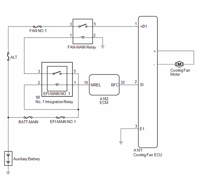
The ECM calculates an appropriate cooling fan speed based on the engine coolant temperature, air conditioning switch status, refrigerant pressure, engine speed and vehicle speed, and sends a signal to the cooling fan ECU (fan with motor assembly). The cooling fan ECU (fan with motor assembly) steplessly control the speed of the cooling fan based on the duty cycle signal sent from the ECM. By sending signals to the cooling fan ECU (fan with motor assembly) in accordance with the driving conditions and by controlling the cooling fan speed optimally with the ECM, both high cooling performance and quietness are ensured.
WIRING DIAGRAM
CAUTION / NOTICE / HINT
NOTICE:
- Inspect the fuses for circuits related to this system before performing the following procedure.
- Before replacing the ECM, refer to Service Bulletin.
PROCEDURE
|
1. | PERFORM ACTIVE TEST USING GTS (CONTROL THE ENGINE COOLING FAN DUTY RATIO) |
(a) Connect the GTS to the DLC3.
(b) Turn the ignition switch to ON.
(c) Turn the GTS on.
(d) Enter the following menus: Powertrain / Engine / Active Test / Control the Engine Cooling Fan Duty Ratio.
Powertrain > Engine > Active Test|
Tester Display |
|---|
| Control the Engine Cooling Fan |
(e) Check the operation of the cooling fan while operating it using the GTS.
OK:
| Tester Operation |
Fan Operation |
|---|---|
| Low/High |
Cooling fan operates |
| OFF |
Cooling fan stops |
| Result |
Proceed to |
|---|---|
| OK |
A |
| Cooling fan does not operate |
B |
| Cooling fan does not stop |
C |
| A |
.gif) | PROCEED TO NEXT SUSPECTED AREA SHOWN IN PROBLEM SYMPTOMS TABLE |
| C |
| GO TO STEP 10 |
|
.gif)
| 2. |
INSPECT COOLING FAN ECU |
(a) Inspect the cooling fan motor.
Click here .gif)
| NG | | REPLACE COOLING FAN MOTOR |
|
| 3. |
CHECK HARNESS AND CONNECTOR (POWER SOURCE CIRCUIT) |
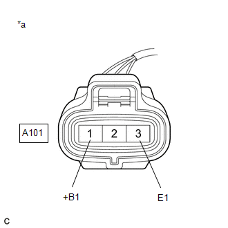
(a) Disconnect the A101 cooling fan ECU connector.
(b) Turn the ignition switch to ON.
| (c) Measure the voltage according to the value(s) in the table below. Standard Voltage: Measure the voltage according to the value(s) in the table below.
|
|
| NG | | GO TO STEP 5 |
|
| 4. |
CHECK HARNESS AND CONNECTOR (ECM - COOLING FAN ECU) |
(a) Disconnect the A182 ECM connector.
(b) Disconnect the A101 cooling fan ECU connector.
(c) Measure the resistance according to the value(s) in the table below.
Standard Resistance (Check for Short):
|
Tester Connection | Condition |
Specified Condition |
|---|---|---|
|
A182-32(RFC) or A101-2(SI) - Body ground |
Always | 10 kΩ or higher |
| OK | | PROCEED TO NEXT SUSPECTED AREA SHOWN IN PROBLEM SYMPTOMS TABLE |
| NG | | REPAIR OR REPLACE HARNESS OR CONNECTOR (ECM - COOLING FAN ECU) |
| 5. |
CHECK HARNESS AND CONNECTOR (COOLING FAN ECU - BODY GROUND) |
(a) Disconnect the A101 cooling fan ECU connector.
(b) Measure the resistance according to the value(s) in the table below.
Standard Resistance (Check for Open):
|
Tester Connection | Condition |
Specified Condition |
|---|---|---|
|
A101-3(E1) - Body ground |
Always | Below 1 Ω |
| NG | | REPAIR OR REPLACE HARNESS OR CONNECTOR (COOLING FAN ECU - BODY GROUND) |
|
| 6. |
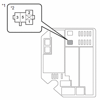
INSPECT FAN-MAIN RELAY |
(a) Inspect the FAN-MAIN relay.
Click here
| NG | | REPLACE FAN-MAIN RELAY |
|
| 7. |
INSPECT HARNESS AND CONNECTOR (POWER SOURCE CIRCUIT) |
| (a) Remove the FAN-MAIN relay from the engine room relay block. |
|
(b) Measure the voltage according to the value(s) in the table below.
Standard Voltage:
|
Tester Connection | Condition |
Specified Condition |
|---|---|---|
|
3 (FAN-MAIN relay) - Body ground |
Always | 11 to 14 V |
| NG | | REPAIR OR REPLACE HARNESS OR CONNECTOR (FAN-MAIN RELAY - AUXILIARY BATTERY) |
|
| 8. |
CHECK HARNESS AND CONNECTOR (COOLING FAN ECU - FAN RELAY) |
(a) Disconnect the A101 cooling fan ECU connector.
(b) Remove the FAN-MAIN relay from the engine room relay block.
(c) Measure the resistance according to the value(s) in the table below.
Standard Resistance (Check for Open):
|
Tester Connection | Condition |
Specified Condition |
|---|---|---|
|
A101-1(+B1) - 5 (FAN-MAIN relay) |
Always | Below 1 Ω |
Standard Resistance (Check for Short):
|
Tester Connection | Condition |
Specified Condition |
|---|---|---|
|
A101-1 (+B1) or 5 (FAN-MAIN relay) - Body ground |
Always | 10 kΩ or higher |
| NG | | REPAIR OR REPLACE HARNESS OR CONNECTOR (COOLING FAN ECU - FAN-MAIN RELAY) |
|
| 9. |
CHECK HARNESS AND CONNECTOR (FAN MAIN RELAY - BODY GROUND) |
(a) Remove the FAN-MAIN relay from the engine room relay block.
(b) Measure the resistance according to the value(s) in the table below.
Standard Resistance:
|
Tester Connection | Condition |
Specified Condition |
|---|---|---|
|
2 (FAN-MAIN relay) - Body ground |
Always | Below 1 Ω |
| OK | | REPAIR OR REPLACE HARNESS OR CONNECTOR (FAN RELAY POWER SOURCE CIRCUIT) |
| NG | | REPAIR OR REPLACE HARNESS OR CONNECTOR (FAN-MAIN RELAY - BODY GROUND) |
| 10. |
CHECK HARNESS AND CONNECTOR (ECM - COOLING FAN ECU) |
(a) Disconnect the A182 ECM connector.
(b) Disconnect the A101 cooling fan ECU connector.
(c) Measure the resistance according to the value(s) in the table below.
Standard Resistance (Check for Open):
|
Tester Connection | Condition |
Specified Condition |
|---|---|---|
|
A182-65(RFC) - A101-2(SI) |
Always | Below 1 Ω |
| NG | | REPAIR OR REPLACE HARNESS OR CONNECTOR (ECM - COOLING FAN ECU) |
|
| 11. |
CHECK HARNESS AND CONNECTOR (COOLING FAN MOTOR - BODY GROUND) |
(a) Disconnect the cooling fan motor connector.
(b) Measure the resistance according to the value(s) in the table below.
Standard Resistance (Check for Short):
|
Tester Connection | Condition |
Specified Condition |
|---|---|---|
|
1(-) - Body ground | Always |
10 kΩ or higher |
| OK | | PROCEED TO NEXT SUSPECTED AREA SHOWN IN PROBLEM SYMPTOMS TABLE |
| NG | | REPLACE COOLING FAN MOTOR |


