Toyota Corolla Cross: Check Bus 5 Line
DESCRIPTION
|
Symptom |
Trouble Area |
|---|---|
|
There are ECUs or sensors that display a communication stop on the bus diagnostic screen. Or, there are ECUs or sensors that display communication stop history on the "Detail" screen. |
|
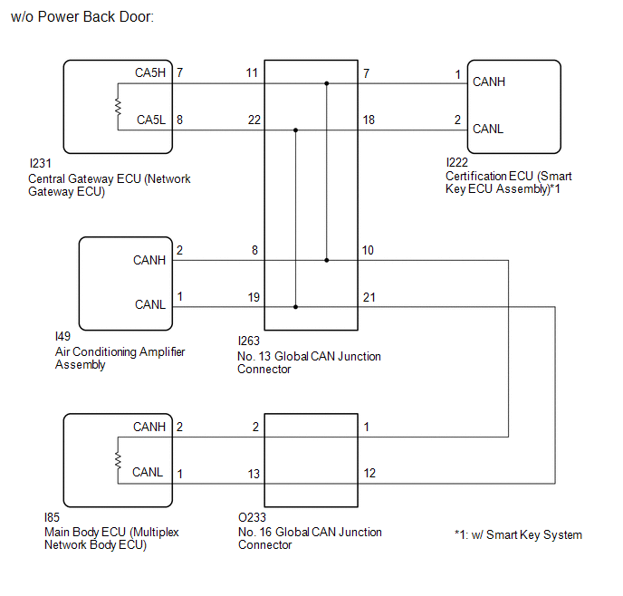
WIRING DIAGRAM
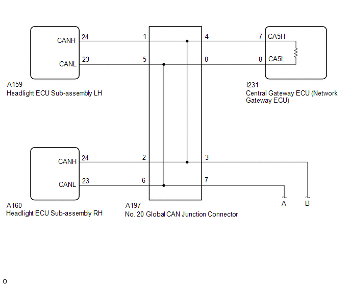
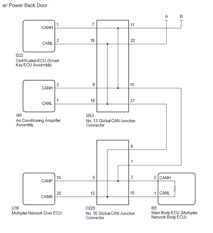
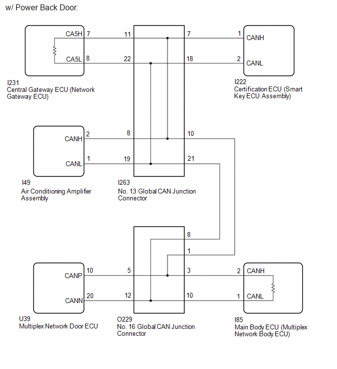
w/ AFS
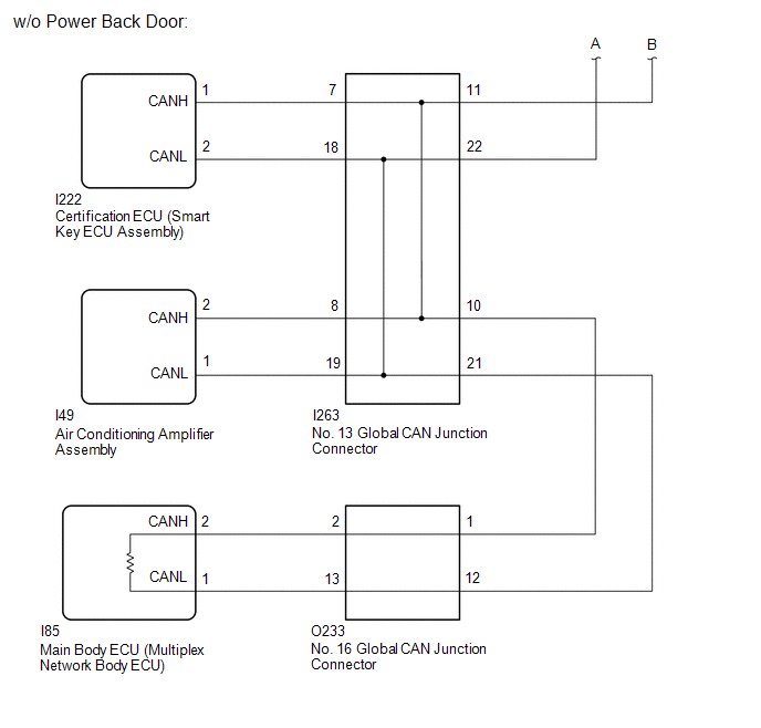
w/o AFS
CAUTION / NOTICE / HINT
CAUTION:
When performing the confirmation driving pattern, obey all speed limits and traffic laws.
NOTICE:
- Because the order of diagnosis is important to allow correct diagnosis,
make sure to begin troubleshooting using How to Proceed with Troubleshooting
when CAN communication system related DTCs are output.
Click here
.gif)
- Before measuring the resistance of the CAN bus, turn the ignition switch off and leave the vehicle for 1 minute or more without operating the key or any switches, or opening or closing the doors. After that, disconnect the cable from the negative (-) auxiliary battery terminal and leave the vehicle for 1 minute or more before measuring the resistance.
- After the ignition switch is turned off, there may be a waiting time before
disconnecting the negative (-) auxiliary battery terminal.
Click here
- When disconnecting and reconnecting the auxiliary battery.
HINT:
When disconnecting and reconnecting the auxiliary battery, there is an automatic learning function that completes learning when the respective system is used.
Click here
- Some parts must be initialized and set when replacing or removing and installing
parts.
Click here
- After performing repairs, perform the DTC check procedure and confirm that
the DTCs are not output again.
DTC check procedure: Turn the ignition switch to ON and wait for 1 minute or more. Then operate the suspected malfunctioning system and drive the vehicle at 60 km/h (37 mph) or more for 5 minutes or more.
- After the repair, perform the CAN bus check and check that all the ECUs
and sensors connected to the CAN communication system are displayed as normal.
Click here
- Before replacing the main body ECU (multiplex network body ECU) or certification
ECU (smart key ECU assembly), refer to Registration.
Click here
HINT:
- Before disconnecting related connectors for inspection, push in on each connector body to check that the connector is not loose or disconnected.
- When a connector is disconnected, check that the terminals and connector body are not cracked, deformed or corroded.
PROCEDURE
|
1. |
CHECK FOR OPEN IN CAN MAIN BUS LINES |
(a) Disconnect the cable from the negative (-) auxiliary battery terminal.
|
(b) Measure the resistance according to the value(s) in the table below. Standard Resistance:
|
|
| NG | .gif) |
GO TO STEP 125 |
|
.gif)
|
2. |
CHECK FOR SHORT IN CAN BUS LINES |
|
(a) Measure the resistance according to the value(s) in the table below. Standard Resistance:
|
|
| NG | |
GO TO STEP 85 |
|
|
3. |
CHECK FOR SHORT TO +B IN CAN BUS LINE |
(a) Measure the resistance according to the value(s) in the table below.
|
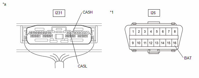
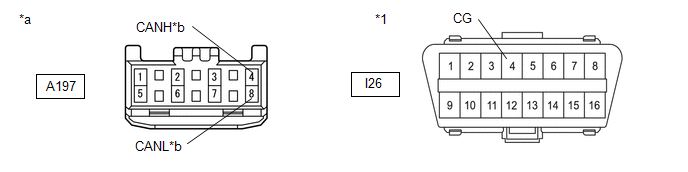
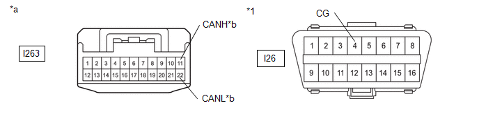
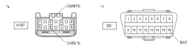
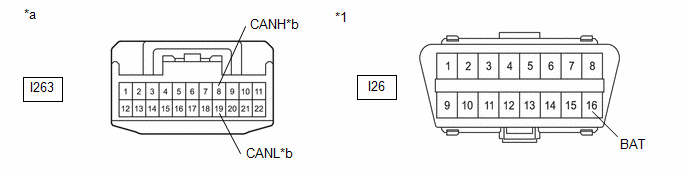
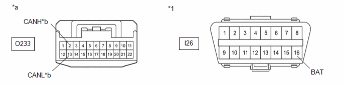
*1 |
DLC3 |
- |
- |
|
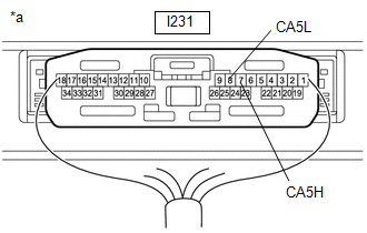
*a |
Component with harness connected (Central Gateway ECU (Network Gateway ECU)) |
- |
- |
Standard Resistance:
|
Tester Connection |
Condition |
Specified Condition |
|---|---|---|
|
I231-7 (CA5H) - I26-16 (BAT) |
Cable disconnected from negative (-) auxiliary battery terminal |
6 kΩ or higher |
|
I231-8 (CA5L) - I26-16 (BAT) |
| NG | |
GO TO STEP 45 |
|
|
4. |
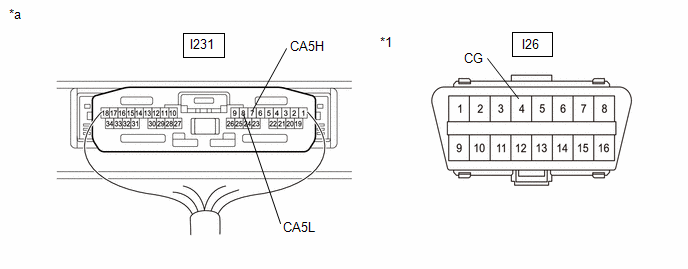
CHECK FOR SHORT TO GND IN CAN BUS LINE |
(a) Measure the resistance according to the value(s) in the table below.
|
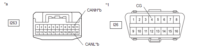
*1 |
DLC3 |
- |
- |
|
*a |
Component with harness connected (Central Gateway ECU (Network Gateway ECU)) |
- |
- |
Standard Resistance:
|
Tester Connection |
Condition |
Specified Condition |
|---|---|---|
|
I231-7 (CA5H) - I26-4 (CG) |
Cable disconnected from negative (-) auxiliary battery terminal |
200 Ω or higher |
|
I231-8 (CA5L) - I26-4 (CG) |
| OK | |
REPLACE CENTRAL GATEWAY ECU (NETWORK GATEWAY ECU) |
|
|
5. |
CHECK VEHICLE TYPE |
(a) Check vehicle type.
|
Result |
Proceed to |
|---|---|
|
w/ AFS |
A |
|
w/o AFS |
B |
| B | |
GO TO STEP 28 |
|
|
6. |
CHECK FOR SHORT TO GND IN CAN BUS LINE (NO. 20 GLOBAL CAN JUNCTION CONNECTOR - CENTRAL GATEWAY ECU (NETWORK GATEWAY ECU)) |
(a) Disconnect the No. 20 global CAN junction connector.
(b) Measure the resistance according to the value(s) in the table below.
|
*1 |
DLC3 |
- |
- |
|
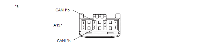
*a |
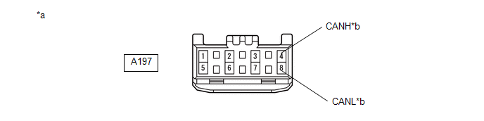
Front view of wire harness connector (to No. 20 Global CAN Junction Connector) |
*b |
to Central Gateway ECU (Network Gateway ECU) |
Standard Resistance:
|
Tester Connection |
Condition |
Specified Condition |
|---|---|---|
|
A197-4 (CANH) - I26-4 (CG) |
Cable disconnected from negative (-) auxiliary battery terminal |
200 Ω or higher |
|
A197-8 (CANL) - I26-4 (CG) |
| NG | |
GO TO STEP 10 |
|
|
7. |
CHECK FOR SHORT TO GND IN CAN BUS LINE (NO. 20 GLOBAL CAN JUNCTION CONNECTOR - NO. 13 GLOBAL CAN JUNCTION CONNECTOR) |
(a) Measure the resistance according to the value(s) in the table below.
|
*1 |
DLC3 |
- |
- |
|
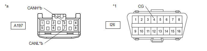
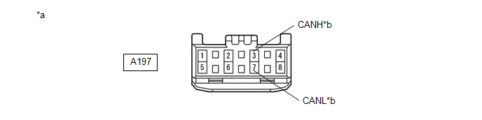
*a |
Front view of wire harness connector (to No. 20 Global CAN Junction Connector) |
*b |
to No. 13 Global CAN Junction Connector |
Standard Resistance:
|
Tester Connection |
Condition |
Specified Condition |
|---|---|---|
|
A197-3 (CANH) - I26-4 (CG) |
Cable disconnected from negative (-) auxiliary battery terminal |
200 Ω or higher |
|
A197-7 (CANL) - I26-4 (CG) |
| NG | |
GO TO STEP 13 |
|
|
8. |
CHECK FOR SHORT TO GND IN CAN BUS LINE (NO. 20 GLOBAL CAN JUNCTION CONNECTOR - HEADLIGHT ECU SUB-ASSEMBLY LH) |
(a) Measure the resistance according to the value(s) in the table below.
|
*1 |
DLC3 |
- |
- |
|
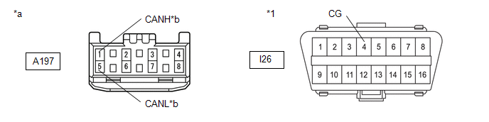
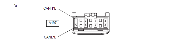
*a |
Front view of wire harness connector (to No. 20 Global CAN Junction Connector) |
*b |
to Headlight ECU Sub-assembly LH |
Standard Resistance:
|
Tester Connection |
Condition |
Specified Condition |
|---|---|---|
|
A197-1 (CANH) - I26-4 (CG) |
Cable disconnected from negative (-) auxiliary battery terminal |
200 Ω or higher |
|
A197-5 (CANL) - I26-4 (CG) |
| NG | |
GO TO STEP 11 |
|
|
9. |
CHECK FOR SHORT TO GND IN CAN BUS LINE (NO. 20 GLOBAL CAN JUNCTION CONNECTOR - HEADLIGHT ECU SUB-ASSEMBLY RH) |
(a) Measure the resistance according to the value(s) in the table below.
|
*1 |
DLC3 |
- |
- |
|
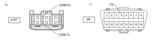
*a |
Front view of wire harness connector (to No. 20 Global CAN Junction Connector) |
*b |
to Headlight ECU Sub-assembly RH |
Standard Resistance:
|
Tester Connection |
Condition |
Specified Condition |
|---|---|---|
|
A197-2 (CANH) - I26-4 (CG) |
Cable disconnected from negative (-) auxiliary battery terminal |
200 Ω or higher |
|
A197-6 (CANL) - I26-4 (CG) |
| OK | |
REPLACE NO. 20 GLOBAL CAN JUNCTION CONNECTOR |
| NG | |
GO TO STEP 12 |
|
10. |
CHECK FOR SHORT TO GND IN CAN BUS LINE (NO. 20 GLOBAL CAN JUNCTION CONNECTOR - CENTRAL GATEWAY ECU (NETWORK GATEWAY ECU)) |
(a) Disconnect the I231 central gateway ECU (network gateway ECU) connector.
(b) Measure the resistance according to the value(s) in the table below.
|
*1 |
DLC3 |
- |
- |
|
*a |
Front view of wire harness connector (to No. 20 Global CAN Junction Connector) |
*b |
to Central Gateway ECU (Network Gateway ECU) |
Standard Resistance:
|
Tester Connection |
Condition |
Specified Condition |
|---|---|---|
|
A197-4 (CANH) - I26-4 (CG) |
Cable disconnected from negative (-) auxiliary battery terminal |
200 Ω or higher |
|
A197-8 (CANL) - I26-4 (CG) |
| OK | |
REPLACE CENTRAL GATEWAY ECU (NETWORK GATEWAY ECU) |
| NG | |
REPAIR OR REPLACE CAN MAIN BUS LINE OR CONNECTOR (NO. 20 GLOBAL CAN JUNCTION CONNECTOR - CENTRAL GATEWAY ECU (NETWORK GATEWAY ECU)) |
|
11. |
CHECK FOR SHORT TO GND IN CAN BUS LINE (NO. 20 GLOBAL CAN JUNCTION CONNECTOR - HEADLIGHT ECU SUB-ASSEMBLY LH) |
(a) Disconnect the A159 headlight ECU sub-assembly LH connector.
(b) Measure the resistance according to the value(s) in the table below.
|
*1 |
DLC3 |
- |
- |
|
*a |
Front view of wire harness connector (to No. 20 Global CAN Junction Connector) |
*b |
to Headlight ECU Sub-assembly LH |
Standard Resistance:
|
Tester Connection |
Condition |
Specified Condition |
|---|---|---|
|
A197-1 (CANH) - I26-4 (CG) |
Cable disconnected from negative (-) auxiliary battery terminal |
200 Ω or higher |
|
A197-5 (CANL) - I26-4 (CG) |
| OK | |
REPLACE HEADLIGHT ECU SUB-ASSEMBLY LH |
| NG | |
REPAIR OR REPLACE CAN BRANCH LINE OR CONNECTOR (NO. 20 GLOBAL CAN JUNCTION CONNECTOR - HEADLIGHT ECU SUB-ASSEMBLY LH) |
|
12. |
CHECK FOR SHORT TO GND IN CAN BUS LINE (NO. 20 GLOBAL CAN JUNCTION CONNECTOR - HEADLIGHT ECU SUB-ASSEMBLY RH) |
(a) Disconnect the A160 headlight ECU sub-assembly RH connector.
(b) Measure the resistance according to the value(s) in the table below.
|
*1 |
DLC3 |
- |
- |
|
*a |
Front view of wire harness connector (to No. 20 Global CAN Junction Connector) |
*b |
to Headlight ECU Sub-assembly RH |
Standard Resistance:
|
Tester Connection |
Condition |
Specified Condition |
|---|---|---|
|
A197-2 (CANH) - I26-4 (CG) |
Cable disconnected from negative (-) auxiliary battery terminal |
200 Ω or higher |
|
A197-6 (CANL) - I26-4 (CG) |
| OK | |
REPLACE HEADLIGHT ECU SUB-ASSEMBLY RH |
| NG | |
REPAIR OR REPLACE CAN BRANCH LINE OR CONNECTOR (NO. 20 GLOBAL CAN JUNCTION CONNECTOR - HEADLIGHT ECU SUB-ASSEMBLY RH) |
|
13. |
CHECK FOR SHORT TO GND IN CAN BUS LINE (NO. 13 GLOBAL CAN JUNCTION CONNECTOR - NO. 20 GLOBAL CAN JUNCTION CONNECTOR) |
(a) Disconnect the No. 13 global CAN junction connector.
(b) Measure the resistance according to the value(s) in the table below.
|
*1 |
DLC3 |
- |
- |
|
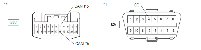
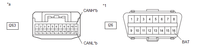
*a |
Front view of wire harness connector (to No. 13 Global CAN Junction Connector) |
*b |
to No. 20 Global CAN Junction Connector |
Standard Resistance:
|
Tester Connection |
Condition |
Specified Condition |
|---|---|---|
|
I263-11 (CANH) - I26-4 (CG) |
Cable disconnected from negative (-) auxiliary battery terminal |
200 Ω or higher |
|
I263-22 (CANL) - I26-4 (CG) |
| NG | |
REPAIR OR REPLACE CAN MAIN BUS LINE OR CONNECTOR (NO. 13 GLOBAL CAN JUNCTION CONNECTOR - NO. 20 GLOBAL CAN JUNCTION CONNECTOR) |
|
|
14. |
CHECK FOR SHORT TO GND IN CAN BUS LINE (NO. 13 GLOBAL CAN JUNCTION CONNECTOR - NO. 16 GLOBAL CAN JUNCTION CONNECTOR) |
(a) Measure the resistance according to the value(s) in the table below.
|
*1 |
DLC3 |
- |
- |
|
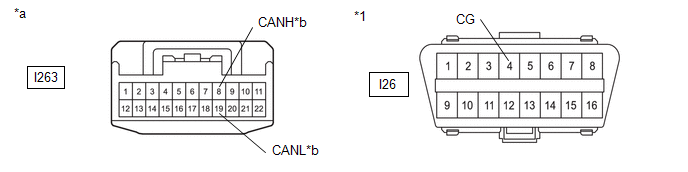
*a |
Front view of wire harness connector (to No. 13 Global CAN Junction Connector) |
*b |
to No. 16 Global CAN Junction Connector |
Standard Resistance:
|
Tester Connection |
Condition |
Specified Condition |
|---|---|---|
|
I263-10 (CANH) - I26-4 (CG) |
Cable disconnected from negative (-) auxiliary battery terminal |
200 Ω or higher |
|
I263-21 (CANL) - I26-4 (CG) |
| NG | |
GO TO STEP 19 |
|
|
15. |
CHECK FOR SHORT TO GND IN CAN BUS LINE (NO. 13 GLOBAL CAN JUNCTION CONNECTOR - CERTIFICATION ECU (SMART KEY ECU ASSEMBLY)) |
(a) Measure the resistance according to the value(s) in the table below.
|
*1 |
DLC3 |
- |
- |
|
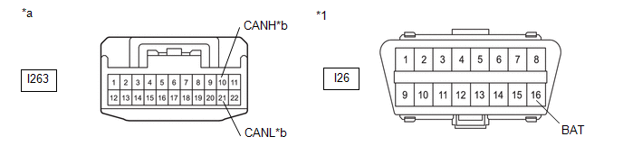
*a |
Front view of wire harness connector (to No. 13 Global CAN Junction Connector) |
*b |
to Certification ECU (Smart Key ECU Assembly) |
Standard Resistance:
|
Tester Connection |
Condition |
Specified Condition |
|---|---|---|
|
I263-7 (CANH) - I26-4 (CG) |
Cable disconnected from negative (-) auxiliary battery terminal |
200 Ω or higher |
|
I263-18 (CANL) - I26-4 (CG) |
| NG | |
GO TO STEP 17 |
|
|
16. |
CHECK FOR SHORT TO GND IN CAN BUS LINE (NO. 13 GLOBAL CAN JUNCTION CONNECTOR - AIR CONDITIONING AMPLIFIER ASSEMBLY) |
(a) Measure the resistance according to the value(s) in the table below.
|
*1 |
DLC3 |
- |
- |
|
*a |
Front view of wire harness connector (to No. 13 Global CAN Junction Connector) |
*b |
to Air Conditioning Amplifier Assembly |
Standard Resistance:
|
Tester Connection |
Condition |
Specified Condition |
|---|---|---|
|
I263-8 (CANH) - I26-4 (CG) |
Cable disconnected from negative (-) auxiliary battery terminal |
200 Ω or higher |
|
I263-19 (CANL) - I26-4 (CG) |
| OK | |
REPLACE NO. 13 GLOBAL CAN JUNCTION CONNECTOR |
| NG | |
GO TO STEP 18 |
|
17. |
CHECK FOR SHORT TO GND IN CAN BUS LINE (NO. 13 GLOBAL CAN JUNCTION CONNECTOR - CERTIFICATION ECU (SMART KEY ECU ASSEMBLY)) |
(a) Disconnect the I222 certification ECU (smart key ECU assembly) connector.
(b) Measure the resistance according to the value(s) in the table below.
|
*1 |
DLC3 |
- |
- |
|
*a |
Front view of wire harness connector (to No. 13 Global CAN Junction Connector) |
*b |
to Certification ECU (Smart Key ECU Assembly) |
Standard Resistance:
|
Tester Connection |
Condition |
Specified Condition |
|---|---|---|
|
I263-7 (CANH) - I26-4 (CG) |
Cable disconnected from negative (-) auxiliary battery terminal |
200 Ω or higher |
|
I263-18 (CANL) - I26-4 (CG) |
| OK | |
REPLACE CERTIFICATION ECU (SMART KEY ECU ASSEMBLY) |
| NG | |
REPAIR OR REPLACE CAN BRANCH LINE OR CONNECTOR (NO. 13 GLOBAL CAN JUNCTION CONNECTOR - CERTIFICATION ECU (SMART KEY ECU ASSEMBLY)) |
|
18. |
CHECK FOR SHORT TO GND IN CAN BUS LINE (NO. 13 GLOBAL CAN JUNCTION CONNECTOR - AIR CONDITIONING AMPLIFIER ASSEMBLY) |
(a) Disconnect the I49 air conditioning amplifier assembly connector.
(b) Measure the resistance according to the value(s) in the table below.
|
*1 |
DLC3 |
- |
- |
|
*a |
Front view of wire harness connector (to No. 13 Global CAN Junction Connector) |
*b |
to Air Conditioning Amplifier Assembly |
Standard Resistance:
|
Tester Connection |
Condition |
Specified Condition |
|---|---|---|
|
I263-8 (CANH) - I26-4 (CG) |
Cable disconnected from negative (-) auxiliary battery terminal |
200 Ω or higher |
|
I263-19 (CANL) - I26-4 (CG) |
| OK | |
REPLACE AIR CONDITIONING AMPLIFIER ASSEMBLY |
| NG | |
REPAIR OR REPLACE CAN BRANCH LINE OR CONNECTOR (NO. 13 GLOBAL CAN JUNCTION CONNECTOR - AIR CONDITIONING AMPLIFIER ASSEMBLY) |
|
19. |
CHECK VEHICLE TYPE |
(a) Check vehicle type.
|
Result |
Proceed to |
|---|---|
|
w/ Power Back Door |
A |
|
w/o Power Back Door |
B |
| B | |
GO TO STEP 25 |
|
|
20. |
CHECK FOR SHORT TO GND IN CAN BUS LINE (NO. 16 GLOBAL CAN JUNCTION CONNECTOR - NO. 13 GLOBAL CAN JUNCTION CONNECTOR) |
(a) Disconnect the No. 16 global CAN junction connector.
(b) Measure the resistance according to the value(s) in the table below.
|
*1 |
DLC3 |
- |
- |
|
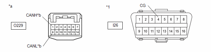
*a |
Front view of wire harness connector (to No. 16 Global CAN Junction Connector) |
*b |
to No. 13 Global CAN Junction Connector |
Standard Resistance:
|
Tester Connection |
Condition |
Specified Condition |
|---|---|---|
|
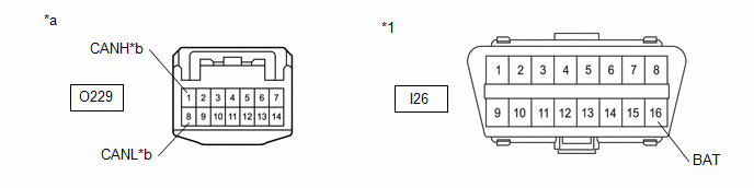
O229-1 (CANH) - I26-4 (CG) |
Cable disconnected from negative (-) auxiliary battery terminal |
200 Ω or higher |
|
O229-8 (CANL) - I26-4 (CG) |
| NG | |
REPAIR OR REPLACE CAN MAIN BUS LINE OR CONNECTOR (NO. 16 GLOBAL CAN JUNCTION CONNECTOR - NO. 13 GLOBAL CAN JUNCTION CONNECTOR) |
|
|
21. |
CHECK FOR SHORT TO GND IN CAN BUS LINE (NO. 16 GLOBAL CAN JUNCTION CONNECTOR - MULTIPLEX NETWORK DOOR ECU) |
(a) Measure the resistance according to the value(s) in the table below.
|
*1 |
DLC3 |
- |
- |
|
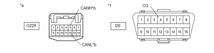
*a |
Front view of wire harness connector (to No. 16 Global CAN Junction Connector) |
*b |
to Multiplex Network Door ECU |
Standard Resistance:
|
Tester Connection |
Condition |
Specified Condition |
|---|---|---|
|
O229-5 (CANH) - I26-4 (CG) |
Cable disconnected from negative (-) auxiliary battery terminal |
200 Ω or higher |
|
O229-12 (CANL) - I26-4 (CG) |
| NG | |
GO TO STEP 23 |
|
|
22. |
CHECK FOR SHORT TO GND IN CAN BUS LINE (NO. 16 GLOBAL CAN JUNCTION CONNECTOR - MAIN BODY ECU (MULTIPLEX NETWORK BODY ECU)) |
(a) Measure the resistance according to the value(s) in the table below.
|
*1 |
DLC3 |
- |
- |
|
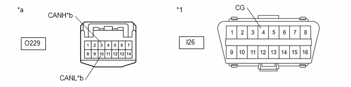
*a |
Front view of wire harness connector (to No. 16 Global CAN Junction Connector) |
*b |
to Main Body ECU (Multiplex Network Body ECU) |
Standard Resistance:
|
Tester Connection |
Condition |
Specified Condition |
|---|---|---|
|
O229-3 (CANH) - I26-4 (CG) |
Cable disconnected from negative (-) auxiliary battery terminal |
200 Ω or higher |
|
O229-10 (CANL) - I26-4 (CG) |
| OK | |
REPLACE NO. 16 GLOBAL CAN JUNCTION CONNECTOR |
| NG | |
GO TO STEP 24 |
|
23. |
CHECK FOR SHORT TO GND IN CAN BUS LINE (NO. 16 GLOBAL CAN JUNCTION CONNECTOR - MULTIPLEX NETWORK DOOR ECU) |
(a) Disconnect the U39 multiplex network door ECU connector.
(b) Measure the resistance according to the value(s) in the table below.
|
*1 |
DLC3 |
- |
- |
|
*a |
Front view of wire harness connector (to No. 16 Global CAN Junction Connector) |
*b |
to Multiplex Network Door ECU |
Standard Resistance:
|
Tester Connection |
Condition |
Specified Condition |
|---|---|---|
|
O229-5 (CANH) - I26-4 (CG) |
Cable disconnected from negative (-) auxiliary battery terminal |
200 Ω or higher |
|
O229-12 (CANL) - I26-4 (CG) |
| OK | |
REPLACE MULTIPLEX NETWORK DOOR ECU |
| NG | |
REPAIR OR REPLACE CAN BRANCH LINE OR CONNECTOR (NO. 16 GLOBAL CAN JUNCTION CONNECTOR - MULTIPLEX NETWORK DOOR ECU) |
|
24. |
CHECK FOR SHORT TO GND IN CAN BUS LINE (NO. 16 GLOBAL CAN JUNCTION CONNECTOR - MAIN BODY ECU (MULTIPLEX NETWORK BODY ECU)) |
(a) Disconnect the I85 main body ECU (multiplex network body ECU) connector.
(b) Measure the resistance according to the value(s) in the table below.
|
*1 |
DLC3 |
- |
- |
|
*a |
Front view of wire harness connector (to No. 16 Global CAN Junction Connector) |
*b |
to Main Body ECU (Multiplex Network Body ECU) |
Standard Resistance:
|
Tester Connection |
Condition |
Specified Condition |
|---|---|---|
|
O229-3 (CANH) - I26-4 (CG) |
Cable disconnected from negative (-) auxiliary battery terminal |
200 Ω or higher |
|
O229-10 (CANL) - I26-4 (CG) |
| OK | |
REPLACE MAIN BODY ECU (MULTIPLEX NETWORK BODY ECU) |
| NG | |
REPAIR OR REPLACE CAN MAIN BUS LINE OR CONNECTOR (NO. 16 GLOBAL CAN JUNCTION CONNECTOR - MAIN BODY ECU (MULTIPLEX NETWORK BODY ECU)) |
|
25. |
CHECK FOR SHORT TO GND IN CAN BUS LINE (NO. 16 GLOBAL CAN JUNCTION CONNECTOR - NO. 13 GLOBAL CAN JUNCTION CONNECTOR) |
(a) Disconnect the No. 16 global CAN junction connector.
(b) Measure the resistance according to the value(s) in the table below.
|
*1 |
DLC3 |
- |
- |
|
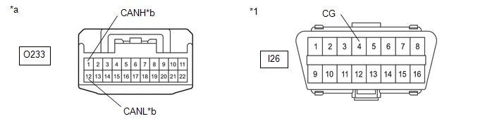
*a |
Front view of wire harness connector (to No. 16 Global CAN Junction Connector) |
*b |
to No. 13 Global CAN Junction Connector |
Standard Resistance:
|
Tester Connection |
Condition |
Specified Condition |
|---|---|---|
|
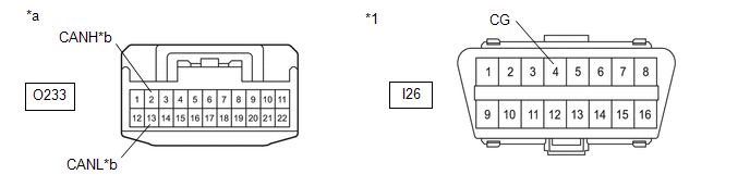
O233-1 (CANH) - I26-4 (CG) |
Cable disconnected from negative (-) auxiliary battery terminal |
200 Ω or higher |
|
O233-12 (CANL) - I26-4 (CG) |
| NG | |
REPAIR OR REPLACE CAN MAIN BUS LINE OR CONNECTOR (NO. 16 GLOBAL CAN JUNCTION CONNECTOR - NO. 13 GLOBAL CAN JUNCTION CONNECTOR) |
|
|
26. |
CHECK FOR SHORT TO GND IN CAN BUS LINE (NO. 16 GLOBAL CAN JUNCTION CONNECTOR - MAIN BODY ECU (MULTIPLEX NETWORK BODY ECU)) |
(a) Measure the resistance according to the value(s) in the table below.
|
*1 |
DLC3 |
- |
- |
|
*a |
Front view of wire harness connector (to No. 16 Global CAN Junction Connector) |
*b |
to Main Body ECU (Multiplex Network Body ECU) |
Standard Resistance:
|
Tester Connection |
Condition |
Specified Condition |
|---|---|---|
|
O233-2 (CANH) - I26-4 (CG) |
Cable disconnected from negative (-) auxiliary battery terminal |
200 Ω or higher |
|
O233-13 (CANL) - I26-4 (CG) |
| OK | |
REPLACE NO. 16 GLOBAL CAN JUNCTION CONNECTOR |
|
|
27. |
CHECK FOR SHORT TO GND IN CAN BUS LINE (NO. 16 GLOBAL CAN JUNCTION CONNECTOR - MAIN BODY ECU (MULTIPLEX NETWORK BODY ECU)) |
(a) Disconnect the I85 main body ECU (multiplex network body ECU) connector.
(b) Measure the resistance according to the value(s) in the table below.
|
*1 |
DLC3 |
- |
- |
|
*a |
Front view of wire harness connector (to No. 16 Global CAN Junction Connector) |
*b |
to Main Body ECU (Multiplex Network Body ECU) |
Standard Resistance:
|
Tester Connection |
Condition |
Specified Condition |
|---|---|---|
|
O233-2 (CANH) - I26-4 (CG) |
Cable disconnected from negative (-) auxiliary battery terminal |
200 Ω or higher |
|
O233-13 (CANL) - I26-4 (CG) |
| OK | |
REPLACE MAIN BODY ECU (MULTIPLEX NETWORK BODY ECU) |
| NG | |
REPAIR OR REPLACE CAN MAIN BUS LINE OR CONNECTOR (NO. 16 GLOBAL CAN JUNCTION CONNECTOR - MAIN BODY ECU (MULTIPLEX NETWORK BODY ECU)) |
|
28. |
CHECK FOR SHORT TO GND IN CAN BUS LINE (NO. 13 GLOBAL CAN JUNCTION CONNECTOR - CENTRAL GATEWAY ECU (NETWORK GATEWAY ECU)) |
(a) Disconnect the No. 13 global CAN junction connector.
(b) Measure the resistance according to the value(s) in the table below.
|
*1 |
DLC3 |
- |
- |
|
*a |
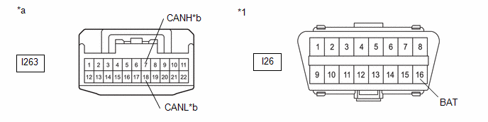
Front view of wire harness connector (to No. 13 Global CAN Junction Connector) |
*b |
to Central Gateway ECU (Network Gateway ECU) |
Standard Resistance:
|
Tester Connection |
Condition |
Specified Condition |
|---|---|---|
|
I263-11 (CANH) - I26-4 (CG) |
Cable disconnected from negative (-) auxiliary battery terminal |
200 Ω or higher |
|
I263-22 (CANL) - I26-4 (CG) |
| NG | |
GO TO STEP 33 |
|
|
29. |
CHECK FOR SHORT TO GND IN CAN BUS LINE (NO. 13 GLOBAL CAN JUNCTION CONNECTOR - NO. 16 GLOBAL CAN JUNCTION CONNECTOR) |
(a) Measure the resistance according to the value(s) in the table below.
|
*1 |
DLC3 |
- |
- |
|
*a |
Front view of wire harness connector (to No. 13 Global CAN Junction Connector) |
*b |
to No. 16 Global CAN Junction Connector |
Standard Resistance:
|
Tester Connection |
Condition |
Specified Condition |
|---|---|---|
|
I263-10 (CANH) - I26-4 (CG) |
Cable disconnected from negative (-) auxiliary battery terminal |
200 Ω or higher |
|
I263-21 (CANL) - I26-4 (CG) |
| NG | |
GO TO STEP 36 |
|
|
30. |
CHECK VEHICLE TYPE |
(a) Check vehicle type.
|
Result |
Proceed to |
|---|---|
|
w/ Smart Key System |
A |
|
w/o Smart Key System |
B |
| B | |
GO TO STEP 32 |
|
|
31. |
CHECK FOR SHORT TO GND IN CAN BUS LINE (NO. 13 GLOBAL CAN JUNCTION CONNECTOR - CERTIFICATION ECU (SMART KEY ECU ASSEMBLY)) |
(a) Measure the resistance according to the value(s) in the table below.
|
*1 |
DLC3 |
- |
- |
|
*a |
Front view of wire harness connector (to No. 13 Global CAN Junction Connector) |
*b |
to Certification ECU (Smart Key ECU Assembly) |
Standard Resistance:
|
Tester Connection |
Condition |
Specified Condition |
|---|---|---|
|
I263-7 (CANH) - I26-4 (CG) |
Cable disconnected from negative (-) auxiliary battery terminal |
200 Ω or higher |
|
I263-18 (CANL) - I26-4 (CG) |
| NG | |
GO TO STEP 34 |
|
|
32. |
CHECK FOR SHORT TO GND IN CAN BUS LINE (NO. 13 GLOBAL CAN JUNCTION CONNECTOR - AIR CONDITIONING AMPLIFIER ASSEMBLY) |
(a) Measure the resistance according to the value(s) in the table below.
|
*1 |
DLC3 |
- |
- |
|
*a |
Front view of wire harness connector (to No. 13 Global CAN Junction Connector) |
*b |
to Air Conditioning Amplifier Assembly |
Standard Resistance:
|
Tester Connection |
Condition |
Specified Condition |
|---|---|---|
|
I263-8 (CANH) - I26-4 (CG) |
Cable disconnected from negative (-) auxiliary battery terminal |
200 Ω or higher |
|
I263-19 (CANL) - I26-4 (CG) |
| OK | |
REPLACE NO. 13 GLOBAL CAN JUNCTION CONNECTOR |
| NG | |
GO TO STEP 35 |
|
33. |
CHECK FOR SHORT TO GND IN CAN BUS LINE (NO. 13 GLOBAL CAN JUNCTION CONNECTOR - CENTRAL GATEWAY ECU (NETWORK GATEWAY ECU)) |
(a) Disconnect the I231 central gateway ECU (network gateway ECU) connector.
(b) Measure the resistance according to the value(s) in the table below.
|
*1 |
DLC3 |
- |
- |
|
*a |
Front view of wire harness connector (to No. 13 Global CAN Junction Connector) |
*b |
to Central Gateway ECU (Network Gateway ECU) |
Standard Resistance:
|
Tester Connection |
Condition |
Specified Condition |
|---|---|---|
|
I263-11 (CANH) - I26-4 (CG) |
Cable disconnected from negative (-) auxiliary battery terminal |
200 Ω or higher |
|
I263-22 (CANL) - I26-4 (CG) |
| OK | |
REPLACE CENTRAL GATEWAY ECU (NETWORK GATEWAY ECU) |
| NG | |
REPAIR OR REPLACE CAN MAIN BUS LINE OR CONNECTOR (NO. 13 GLOBAL CAN JUNCTION CONNECTOR - CENTRAL GATEWAY ECU (NETWORK GATEWAY ECU)) |
|
34. |
CHECK FOR SHORT TO GND IN CAN BUS LINE (NO. 13 GLOBAL CAN JUNCTION CONNECTOR - CERTIFICATION ECU (SMART KEY ECU ASSEMBLY)) |
(a) Disconnect the I222 certification ECU (smart key ECU assembly) connector.
(b) Measure the resistance according to the value(s) in the table below.
|
*1 |
DLC3 |
- |
- |
|
*a |
Front view of wire harness connector (to No. 13 Global CAN Junction Connector) |
*b |
to Certification ECU (Smart Key ECU Assembly) |
Standard Resistance:
|
Tester Connection |
Condition |
Specified Condition |
|---|---|---|
|
I263-7 (CANH) - I26-4 (CG) |
Cable disconnected from negative (-) auxiliary battery terminal |
200 Ω or higher |
|
I263-18 (CANL) - I26-4 (CG) |
| OK | |
REPLACE CERTIFICATION ECU (SMART KEY ECU ASSEMBLY) |
| NG | |
REPAIR OR REPLACE CAN BRANCH LINE OR CONNECTOR (NO. 13 GLOBAL CAN JUNCTION CONNECTOR - CERTIFICATION ECU (SMART KEY ECU ASSEMBLY)) |
|
35. |
CHECK FOR SHORT TO GND IN CAN BUS LINE (NO. 13 GLOBAL CAN JUNCTION CONNECTOR - AIR CONDITIONING AMPLIFIER ASSEMBLY) |
(a) Disconnect the I49 air conditioning amplifier assembly connector.
(b) Measure the resistance according to the value(s) in the table below.
|
*1 |
DLC3 |
- |
- |
|
*a |
Front view of wire harness connector (to No. 13 Global CAN Junction Connector) |
*b |
to Air Conditioning Amplifier Assembly |
Standard Resistance:
|
Tester Connection |
Condition |
Specified Condition |
|---|---|---|
|
I263-8 (CANH) - I26-4 (CG) |
Cable disconnected from negative (-) auxiliary battery terminal |
200 Ω or higher |
|
I263-19 (CANL) - I26-4 (CG) |
| OK | |
REPLACE AIR CONDITIONING AMPLIFIER ASSEMBLY |
| NG | |
REPAIR OR REPLACE CAN BRANCH LINE OR CONNECTOR (NO. 13 GLOBAL CAN JUNCTION CONNECTOR - AIR CONDITIONING AMPLIFIER ASSEMBLY) |
|
36. |
CHECK VEHICLE TYPE |
(a) Check vehicle type.
|
Result |
Proceed to |
|---|---|
|
w/ Power Back Door |
A |
|
w/o Power Back Door |
B |
| B | |
GO TO STEP 42 |
|
|
37. |
CHECK FOR SHORT TO GND IN CAN BUS LINE (NO. 16 GLOBAL CAN JUNCTION CONNECTOR - NO. 13 GLOBAL CAN JUNCTION CONNECTOR) |
(a) Disconnect the No. 16 global CAN junction connector.
(b) Measure the resistance according to the value(s) in the table below.
|
*1 |
DLC3 |
- |
- |
|
*a |
Front view of wire harness connector (to No. 16 Global CAN Junction Connector) |
*b |
to No. 13 Global CAN Junction Connector |
Standard Resistance:
|
Tester Connection |
Condition |
Specified Condition |
|---|---|---|
|
O229-1 (CANH) - I26-4 (CG) |
Cable disconnected from negative (-) auxiliary battery terminal |
200 Ω or higher |
|
O229-8 (CANL) - I26-4 (CG) |
| NG | |
REPAIR OR REPLACE CAN MAIN BUS LINE OR CONNECTOR (NO. 16 GLOBAL CAN JUNCTION CONNECTOR - NO. 13 GLOBAL CAN JUNCTION CONNECTOR) |
|
|
38. |
CHECK FOR SHORT TO GND IN CAN BUS LINE (NO. 16 GLOBAL CAN JUNCTION CONNECTOR - MULTIPLEX NETWORK DOOR ECU) |
(a) Measure the resistance according to the value(s) in the table below.
|
*1 |
DLC3 |
- |
- |
|
*a |
Front view of wire harness connector (to No. 16 Global CAN Junction Connector) |
*b |
to Multiplex Network Door ECU |
Standard Resistance:
|
Tester Connection |
Condition |
Specified Condition |
|---|---|---|
|
O229-5 (CANH) - I26-4 (CG) |
Cable disconnected from negative (-) auxiliary battery terminal |
200 Ω or higher |
|
O229-12 (CANL) - I26-4 (CG) |
| NG | |
GO TO STEP 40 |
|
|
39. |
CHECK FOR SHORT TO GND IN CAN BUS LINE (NO. 16 GLOBAL CAN JUNCTION CONNECTOR - MAIN BODY ECU (MULTIPLEX NETWORK BODY ECU)) |
(a) Measure the resistance according to the value(s) in the table below.
|
*1 |
DLC3 |
- |
- |
|
*a |
Front view of wire harness connector (to No. 16 Global CAN Junction Connector) |
*b |
to Main Body ECU (Multiplex Network Body ECU) |
Standard Resistance:
|
Tester Connection |
Condition |
Specified Condition |
|---|---|---|
|
O229-3 (CANH) - I26-4 (CG) |
Cable disconnected from negative (-) auxiliary battery terminal |
200 Ω or higher |
|
O229-10 (CANL) - I26-4 (CG) |
| OK | |
REPLACE NO. 16 GLOBAL CAN JUNCTION CONNECTOR |
| NG | |
GO TO STEP 41 |
|
40. |
CHECK FOR SHORT TO GND IN CAN BUS LINE (NO. 16 GLOBAL CAN JUNCTION CONNECTOR - MULTIPLEX NETWORK DOOR ECU) |
(a) Disconnect the U39 multiplex network door ECU connector.
(b) Measure the resistance according to the value(s) in the table below.
|
*1 |
DLC3 |
- |
- |
|
*a |
Front view of wire harness connector (to No. 16 Global CAN Junction Connector) |
*b |
to Multiplex Network Door ECU |
Standard Resistance:
|
Tester Connection |
Condition |
Specified Condition |
|---|---|---|
|
O229-5 (CANH) - I26-4 (CG) |
Cable disconnected from negative (-) auxiliary battery terminal |
200 Ω or higher |
|
O229-12 (CANL) - I26-4 (CG) |
| OK | |
REPLACE MULTIPLEX NETWORK DOOR ECU |
| NG | |
REPAIR OR REPLACE CAN BRANCH LINE OR CONNECTOR (NO. 16 GLOBAL CAN JUNCTION CONNECTOR - MULTIPLEX NETWORK DOOR ECU) |
|
41. |
CHECK FOR SHORT TO GND IN CAN BUS LINE (NO. 16 GLOBAL CAN JUNCTION CONNECTOR - MAIN BODY ECU (MULTIPLEX NETWORK BODY ECU)) |
(a) Disconnect the I85 main body ECU (multiplex network body ECU) connector.
(b) Measure the resistance according to the value(s) in the table below.
|
*1 |
DLC3 |
- |
- |
|
*a |
Front view of wire harness connector (to No. 16 Global CAN Junction Connector) |
*b |
to Main Body ECU (Multiplex Network Body ECU) |
Standard Resistance:
|
Tester Connection |
Condition |
Specified Condition |
|---|---|---|
|
O229-3 (CANH) - I26-4 (CG) |
Cable disconnected from negative (-) auxiliary battery terminal |
200 Ω or higher |
|
O229-10 (CANL) - I26-4 (CG) |
| OK | |
REPLACE MAIN BODY ECU (MULTIPLEX NETWORK BODY ECU) |
| NG | |
REPAIR OR REPLACE CAN MAIN BUS LINE OR CONNECTOR (NO. 16 GLOBAL CAN JUNCTION CONNECTOR - MAIN BODY ECU (MULTIPLEX NETWORK BODY ECU)) |
|
42. |
CHECK FOR SHORT TO GND IN CAN BUS LINE (NO. 16 GLOBAL CAN JUNCTION CONNECTOR - NO. 13 GLOBAL CAN JUNCTION CONNECTOR) |
(a) Disconnect the No. 16 global CAN junction connector.
(b) Measure the resistance according to the value(s) in the table below.
|
*1 |
DLC3 |
- |
- |
|
*a |
Front view of wire harness connector (to No. 16 Global CAN Junction Connector) |
*b |
to No. 13 Global CAN Junction Connector |
Standard Resistance:
|
Tester Connection |
Condition |
Specified Condition |
|---|---|---|
|
O233-1 (CANH) - I26-4 (CG) |
Cable disconnected from negative (-) auxiliary battery terminal |
200 Ω or higher |
|
O233-12 (CANL) - I26-4 (CG) |
| NG | |
REPAIR OR REPLACE CAN MAIN BUS LINE OR CONNECTOR (NO. 16 GLOBAL CAN JUNCTION CONNECTOR - NO. 13 GLOBAL CAN JUNCTION CONNECTOR) |
|
|
43. |
CHECK FOR SHORT TO GND IN CAN BUS LINE (NO. 16 GLOBAL CAN JUNCTION CONNECTOR - MAIN BODY ECU (MULTIPLEX NETWORK BODY ECU)) |
(a) Measure the resistance according to the value(s) in the table below.
|
*1 |
DLC3 |
- |
- |
|
*a |
Front view of wire harness connector (to No. 16 Global CAN Junction Connector) |
*b |
to Main Body ECU (Multiplex Network Body ECU) |
Standard Resistance:
|
Tester Connection |
Condition |
Specified Condition |
|---|---|---|
|
O233-2 (CANH) - I26-4 (CG) |
Cable disconnected from negative (-) auxiliary battery terminal |
200 Ω or higher |
|
O233-13 (CANL) - I26-4 (CG) |
| OK | |
REPLACE NO. 16 GLOBAL CAN JUNCTION CONNECTOR |
|
|
44. |
CHECK FOR SHORT TO GND IN CAN BUS LINE (NO. 16 GLOBAL CAN JUNCTION CONNECTOR - MAIN BODY ECU (MULTIPLEX NETWORK BODY ECU)) |
(a) Disconnect the I85 main body ECU (multiplex network body ECU) connector.
(b) Measure the resistance according to the value(s) in the table below.
|
*1 |
DLC3 |
- |
- |
|
*a |
Front view of wire harness connector (to No. 16 Global CAN Junction Connector) |
*b |
to Main Body ECU (Multiplex Network Body ECU) |
Standard Resistance:
|
Tester Connection |
Condition |
Specified Condition |
|---|---|---|
|
O233-2 (CANH) - I26-4 (CG) |
Cable disconnected from negative (-) auxiliary battery terminal |
200 Ω or higher |
|
O233-13 (CANL) - I26-4 (CG) |
| OK | |
REPLACE MAIN BODY ECU (MULTIPLEX NETWORK BODY ECU) |
| NG | |
REPAIR OR REPLACE CAN MAIN BUS LINE OR CONNECTOR (NO. 16 GLOBAL CAN JUNCTION CONNECTOR - MAIN BODY ECU (MULTIPLEX NETWORK BODY ECU)) |
|
45. |
CHECK VEHICLE TYPE |
(a) Check vehicle type.
|
Result |
Proceed to |
|---|---|
|
w/ AFS |
A |
|
w/o AFS |
B |
| B | |
GO TO STEP 68 |
|
|
46. |
CHECK FOR SHORT TO +B IN CAN BUS LINE (NO. 20 GLOBAL CAN JUNCTION CONNECTOR - CENTRAL GATEWAY ECU (NETWORK GATEWAY ECU)) |
(a) Disconnect the No. 20 global CAN junction connector.
(b) Measure the resistance according to the value(s) in the table below.
|
*1 |
DLC3 |
- |
- |
|
*a |
Front view of wire harness connector (to No. 20 Global CAN Junction Connector) |
*b |
to Central Gateway ECU (Network Gateway ECU) |
Standard Resistance:
|
Tester Connection |
Condition |
Specified Condition |
|---|---|---|
|
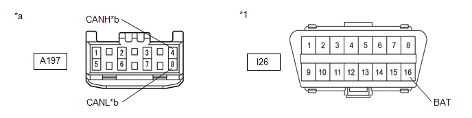
A197-4 (CANH) - I26-16 (BAT) |
Cable disconnected from negative (-) auxiliary battery terminal |
6 kΩ or higher |
|
A197-8 (CANL) - I26-16 (BAT) |
| NG | |
GO TO STEP 50 |
|
|
47. |
CHECK FOR SHORT TO +B IN CAN BUS LINE (NO. 20 GLOBAL CAN JUNCTION CONNECTOR - NO. 13 GLOBAL CAN JUNCTION CONNECTOR) |
(a) Measure the resistance according to the value(s) in the table below.
|
*1 |
DLC3 |
- |
- |
|
*a |
Front view of wire harness connector (to No. 20 Global CAN Junction Connector) |
*b |
to No. 13 Global CAN Junction Connector |
Standard Resistance:
|
Tester Connection |
Condition |
Specified Condition |
|---|---|---|
|
A197-3 (CANH) - I26-16 (BAT) |
Cable disconnected from negative (-) auxiliary battery terminal |
6 kΩ or higher |
|
A197-7 (CANL) - I26-16 (BAT) |
| NG | |
GO TO STEP 53 |
|
|
48. |
CHECK FOR SHORT TO +B IN CAN BUS LINE (NO. 20 GLOBAL CAN JUNCTION CONNECTOR - HEADLIGHT ECU SUB-ASSEMBLY LH) |
(a) Measure the resistance according to the value(s) in the table below.
|
*1 |
DLC3 |
- |
- |
|
*a |
Front view of wire harness connector (to No. 20 Global CAN Junction Connector) |
*b |
to Headlight ECU Sub-assembly LH |
Standard Resistance:
|
Tester Connection |
Condition |
Specified Condition |
|---|---|---|
|
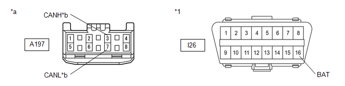
A197-1 (CANH) - I26-16 (BAT) |
Cable disconnected from negative (-) auxiliary battery terminal |
6 kΩ or higher |
|
A197-5 (CANL) - I26-16 (BAT) |
| NG | |
GO TO STEP 51 |
|
|
49. |
CHECK FOR SHORT TO +B IN CAN BUS LINE (NO. 20 GLOBAL CAN JUNCTION CONNECTOR - HEADLIGHT ECU SUB-ASSEMBLY RH) |
(a) Measure the resistance according to the value(s) in the table below.
|
*1 |
DLC3 |
- |
- |
|
*a |
Front view of wire harness connector (to No. 20 Global CAN Junction Connector) |
*b |
to Headlight ECU Sub-assembly RH |
Standard Resistance:
|
Tester Connection |
Condition |
Specified Condition |
|---|---|---|
|
A197-2 (CANH) - I26-16 (BAT) |
Cable disconnected from negative (-) auxiliary battery terminal |
6 kΩ or higher |
|
A197-6 (CANL) - I26-16 (BAT) |
| OK | |
REPLACE NO. 20 GLOBAL CAN JUNCTION CONNECTOR |
| NG | |
GO TO STEP 52 |
|
50. |
CHECK FOR SHORT TO +B IN CAN BUS LINE (NO. 20 GLOBAL CAN JUNCTION CONNECTOR - CENTRAL GATEWAY ECU (NETWORK GATEWAY ECU)) |
(a) Disconnect the I231 central gateway ECU (network gateway ECU) connector.
(b) Measure the resistance according to the value(s) in the table below.
|
*1 |
DLC3 |
- |
- |
|
*a |
Front view of wire harness connector (to No. 20 Global CAN Junction Connector) |
*b |
to Central Gateway ECU (Network Gateway ECU) |
Standard Resistance:
|
Tester Connection |
Condition |
Specified Condition |
|---|---|---|
|
A197-4 (CANH) - I26-16 (BAT) |
Cable disconnected from negative (-) auxiliary battery terminal |
6 kΩ or higher |
|
A197-8 (CANL) - I26-16 (BAT) |
| OK | |
REPLACE CENTRAL GATEWAY ECU (NETWORK GATEWAY ECU) |
| NG | |
REPAIR OR REPLACE CAN MAIN BUS LINE OR CONNECTOR (NO. 20 GLOBAL CAN JUNCTION CONNECTOR - CENTRAL GATEWAY ECU (NETWORK GATEWAY ECU)) |
|
51. |
CHECK FOR SHORT TO +B IN CAN BUS LINE (NO. 20 GLOBAL CAN JUNCTION CONNECTOR - HEADLIGHT ECU SUB-ASSEMBLY LH) |
(a) Disconnect the A159 headlight ECU sub-assembly LH connector.
(b) Measure the resistance according to the value(s) in the table below.
|
*1 |
DLC3 |
- |
- |
|
*a |
Front view of wire harness connector (to No. 20 Global CAN Junction Connector) |
*b |
to Headlight ECU Sub-assembly LH |
Standard Resistance:
|
Tester Connection |
Condition |
Specified Condition |
|---|---|---|
|
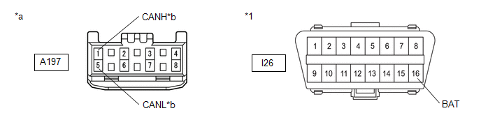
A197-1 (CANH) - I26-16 (BAT) |
Cable disconnected from negative (-) auxiliary battery terminal |
6 kΩ or higher |
|
A197-5 (CANL) - I26-16 (BAT) |
| OK | |
REPLACE HEADLIGHT ECU SUB-ASSEMBLY LH |
| NG | |
REPAIR OR REPLACE CAN BRANCH LINE OR CONNECTOR (NO. 20 GLOBAL CAN JUNCTION CONNECTOR - HEADLIGHT ECU SUB-ASSEMBLY LH) |
|
52. |
CHECK FOR SHORT TO +B IN CAN BUS LINE (NO. 20 GLOBAL CAN JUNCTION CONNECTOR - HEADLIGHT ECU SUB-ASSEMBLY RH) |
(a) Disconnect the A160 headlight ECU sub-assembly RH connector.
(b) Measure the resistance according to the value(s) in the table below.
|
*1 |
DLC3 |
- |
- |
|
*a |
Front view of wire harness connector (to No. 20 Global CAN Junction Connector) |
*b |
to Headlight ECU Sub-assembly RH |
Standard Resistance:
|
Tester Connection |
Condition |
Specified Condition |
|---|---|---|
|
A197-2 (CANH) - I26-16 (BAT) |
Cable disconnected from negative (-) auxiliary battery terminal |
6 kΩ or higher |
|
A197-6 (CANL) - I26-16 (BAT) |
| OK | |
REPLACE HEADLIGHT ECU SUB-ASSEMBLY RH |
| NG | |
REPAIR OR REPLACE CAN BRANCH LINE OR CONNECTOR (NO. 20 GLOBAL CAN JUNCTION CONNECTOR - HEADLIGHT ECU SUB-ASSEMBLY RH) |
|
53. |
CHECK FOR SHORT TO +B IN CAN BUS LINE (NO. 13 GLOBAL CAN JUNCTION CONNECTOR - NO. 20 GLOBAL CAN JUNCTION CONNECTOR) |
(a) Disconnect the No. 13 global CAN junction connector.
(b) Measure the resistance according to the value(s) in the table below.
|
*1 |
DLC3 |
- |
- |
|
*a |
Front view of wire harness connector (to No. 13 Global CAN Junction Connector) |
*b |
to No. 20 Global CAN Junction Connector |
Standard Resistance:
|
Tester Connection |
Condition |
Specified Condition |
|---|---|---|
|
I263-11 (CANH) - I26-16 (BAT) |
Cable disconnected from negative (-) auxiliary battery terminal |
6 kΩ or higher |
|
I263-22 (CANL) - I26-16 (BAT) |
| NG | |
REPAIR OR REPLACE CAN MAIN BUS LINE OR CONNECTOR (NO. 13 GLOBAL CAN JUNCTION CONNECTOR - NO. 20 GLOBAL CAN JUNCTION CONNECTOR) |
|
|
54. |
CHECK FOR SHORT TO +B IN CAN BUS LINE (NO. 13 GLOBAL CAN JUNCTION CONNECTOR - NO. 16 GLOBAL CAN JUNCTION CONNECTOR) |
(a) Measure the resistance according to the value(s) in the table below.
|
*1 |
DLC3 |
- |
- |
|
*a |
Front view of wire harness connector (to No. 13 Global CAN Junction Connector) |
*b |
to No. 16 Global CAN Junction Connector |
Standard Resistance:
|
Tester Connection |
Condition |
Specified Condition |
|---|---|---|
|
I263-10 (CANH) - I26-16 (BAT) |
Cable disconnected from negative (-) auxiliary battery terminal |
6 kΩ or higher |
|
I263-21 (CANL) - I26-16 (BAT) |
| NG | |
GO TO STEP 59 |
|
|
55. |
CHECK FOR SHORT TO +B IN CAN BUS LINE (NO. 13 GLOBAL CAN JUNCTION CONNECTOR - CERTIFICATION ECU (SMART KEY ECU ASSEMBLY)) |
(a) Measure the resistance according to the value(s) in the table below.
|
*1 |
DLC3 |
- |
- |
|
*a |
Front view of wire harness connector (to No. 13 Global CAN Junction Connector) |
*b |
to Certification ECU (Smart Key ECU Assembly) |
Standard Resistance:
|
Tester Connection |
Condition |
Specified Condition |
|---|---|---|
|
I263-7 (CANH) - I26-16 (BAT) |
Cable disconnected from negative (-) auxiliary battery terminal |
6 kΩ or higher |
|
I263-18 (CANL) - I26-16 (BAT) |
| NG | |
GO TO STEP 57 |
|
|
56. |
CHECK FOR SHORT TO +B IN CAN BUS LINE (NO. 13 GLOBAL CAN JUNCTION CONNECTOR - AIR CONDITIONING AMPLIFIER ASSEMBLY) |
(a) Measure the resistance according to the value(s) in the table below.
|
*1 |
DLC3 |
- |
- |
|
*a |
Front view of wire harness connector (to No. 13 Global CAN Junction Connector) |
*b |
to Air Conditioning Amplifier Assembly |
Standard Resistance:
|
Tester Connection |
Condition |
Specified Condition |
|---|---|---|
|
I263-8 (CANH) - I26-16 (BAT) |
Cable disconnected from negative (-) auxiliary battery terminal |
6 kΩ or higher |
|
I263-19 (CANL) - I26-16 (BAT) |
| OK | |
REPLACE NO. 13 GLOBAL CAN JUNCTION CONNECTOR |
| NG | |
GO TO STEP 58 |
|
57. |
CHECK FOR SHORT TO +B IN CAN BUS LINE (NO. 13 GLOBAL CAN JUNCTION CONNECTOR - CERTIFICATION ECU (SMART KEY ECU ASSEMBLY)) |
(a) Disconnect the I222 certification ECU (smart key ECU assembly) connector.
(b) Measure the resistance according to the value(s) in the table below.
|
*1 |
DLC3 |
- |
- |
|
*a |
Front view of wire harness connector (to No. 13 Global CAN Junction Connector) |
*b |
to Certification ECU (Smart Key ECU Assembly) |
Standard Resistance:
|
Tester Connection |
Condition |
Specified Condition |
|---|---|---|
|
I263-7 (CANH) - I26-16 (BAT) |
Cable disconnected from negative (-) auxiliary battery terminal |
6 kΩ or higher |
|
I263-18 (CANL) - I26-16 (BAT) |
| OK | |
REPLACE CERTIFICATION ECU (SMART KEY ECU ASSEMBLY) |
| NG | |
REPAIR OR REPLACE CAN BRANCH LINE OR CONNECTOR (NO. 13 GLOBAL CAN JUNCTION CONNECTOR - CERTIFICATION ECU (SMART KEY ECU ASSEMBLY)) |
|
58. |
CHECK FOR SHORT TO +B IN CAN BUS LINE (NO. 13 GLOBAL CAN JUNCTION CONNECTOR - AIR CONDITIONING AMPLIFIER ASSEMBLY) |
(a) Disconnect the I49 air conditioning amplifier assembly connector.
(b) Measure the resistance according to the value(s) in the table below.
|
*1 |
DLC3 |
- |
- |
|
*a |
Front view of wire harness connector (to No. 13 Global CAN Junction Connector) |
*b |
to Air Conditioning Amplifier Assembly |
Standard Resistance:
|
Tester Connection |
Condition |
Specified Condition |
|---|---|---|
|
I263-8 (CANH) - I26-16 (BAT) |
Cable disconnected from negative (-) auxiliary battery terminal |
6 kΩ or higher |
|
I263-19 (CANL) - I26-16 (BAT) |
| OK | |
REPLACE AIR CONDITIONING AMPLIFIER ASSEMBLY |
| NG | |
REPAIR OR REPLACE CAN BRANCH LINE OR CONNECTOR (NO. 13 GLOBAL CAN JUNCTION CONNECTOR - AIR CONDITIONING AMPLIFIER ASSEMBLY) |
|
59. |
CHECK VEHICLE TYPE |
(a) Check vehicle type.
|
Result |
Proceed to |
|---|---|
|
w/ Power Back Door |
A |
|
w/o Power Back Door |
B |
| B | |
GO TO STEP 65 |
|
|
60. |
CHECK FOR SHORT TO +B IN CAN BUS LINE (NO. 16 GLOBAL CAN JUNCTION CONNECTOR - NO. 13 GLOBAL CAN JUNCTION CONNECTOR) |
(a) Disconnect the No. 16 global CAN junction connector.
(b) Measure the resistance according to the value(s) in the table below.
|
*1 |
DLC3 |
- |
- |
|
*a |
Front view of wire harness connector (to No. 16 Global CAN Junction Connector) |
*b |
to No. 13 Global CAN Junction Connector |
Standard Resistance:
|
Tester Connection |
Condition |
Specified Condition |
|---|---|---|
|
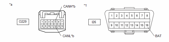
O229-1 (CANH) - I26-16 (BAT) |
Cable disconnected from negative (-) auxiliary battery terminal |
6 kΩ or higher |
|
O229-8 (CANL) - I26-16 (BAT) |
| NG | |
REPAIR OR REPLACE CAN MAIN BUS LINE OR CONNECTOR (NO. 16 GLOBAL CAN JUNCTION CONNECTOR - NO. 13 GLOBAL CAN JUNCTION CONNECTOR) |
|
|
61. |
CHECK FOR SHORT TO +B IN CAN BUS LINE (NO. 16 GLOBAL CAN JUNCTION CONNECTOR - MULTIPLEX NETWORK DOOR ECU) |
(a) Measure the resistance according to the value(s) in the table below.
|
*1 |
DLC3 |
- |
- |
|
*a |
Front view of wire harness connector (to No. 16 Global CAN Junction Connector) |
*b |
to Multiplex Network Door ECU |
Standard Resistance:
|
Tester Connection |
Condition |
Specified Condition |
|---|---|---|
|
O229-5 (CANH) - I26-16 (BAT) |
Cable disconnected from negative (-) auxiliary battery terminal |
6 kΩ or higher |
|
O229-12 (CANL) - I26-16 (BAT) |
| NG | |
GO TO STEP 63 |
|
|
62. |
CHECK FOR SHORT TO +B IN CAN BUS LINE (NO. 16 GLOBAL CAN JUNCTION CONNECTOR - MAIN BODY ECU (MULTIPLEX NETWORK BODY ECU)) |
(a) Measure the resistance according to the value(s) in the table below.
|
*1 |
DLC3 |
- |
- |
|
*a |
Front view of wire harness connector (to No. 16 Global CAN Junction Connector) |
*b |
to Main Body ECU (Multiplex Network Body ECU) |
Standard Resistance:
|
Tester Connection |
Condition |
Specified Condition |
|---|---|---|
|
O229-3 (CANH) - I26-16 (BAT) |
Cable disconnected from negative (-) auxiliary battery terminal |
6 kΩ or higher |
|
O229-10 (CANL) - I26-16 (BAT) |
| OK | |
REPLACE NO. 16 GLOBAL CAN JUNCTION CONNECTOR |
| NG | |
GO TO STEP 64 |
|
63. |
CHECK FOR SHORT TO +B IN CAN BUS LINE (NO. 16 GLOBAL CAN JUNCTION CONNECTOR - MULTIPLEX NETWORK DOOR ECU) |
(a) Disconnect the U39 multiplex network door ECU connector.
(b) Measure the resistance according to the value(s) in the table below.
|
*1 |
DLC3 |
- |
- |
|
*a |
Front view of wire harness connector (to No. 16 Global CAN Junction Connector) |
*b |
to Multiplex Network Door ECU |
Standard Resistance:
|
Tester Connection |
Condition |
Specified Condition |
|---|---|---|
|
O229-5 (CANH) - I26-16 (BAT) |
Cable disconnected from negative (-) auxiliary battery terminal |
6 kΩ or higher |
|
O229-12 (CANL) - I26-16 (BAT) |
| OK | |
REPLACE MULTIPLEX NETWORK DOOR ECU |
| NG | |
REPAIR OR REPLACE CAN BRANCH LINE OR CONNECTOR (NO. 16 GLOBAL CAN JUNCTION CONNECTOR - MULTIPLEX NETWORK DOOR ECU) |
|
64. |
CHECK FOR SHORT TO +B IN CAN BUS LINE (NO. 16 GLOBAL CAN JUNCTION CONNECTOR - MAIN BODY ECU (MULTIPLEX NETWORK BODY ECU)) |
(a) Disconnect the I85 main body ECU (multiplex network body ECU) connector.
(b) Measure the resistance according to the value(s) in the table below.
|
*1 |
DLC3 |
- |
- |
|
*a |
Front view of wire harness connector (to No. 16 Global CAN Junction Connector) |
*b |
to Main Body ECU (Multiplex Network Body ECU) |
Standard Resistance:
|
Tester Connection |
Condition |
Specified Condition |
|---|---|---|
|
O229-3 (CANH) - I26-16 (BAT) |
Cable disconnected from negative (-) auxiliary battery terminal |
6 kΩ or higher |
|
O229-10 (CANL) - I26-16 (BAT) |
| OK | |
REPLACE MAIN BODY ECU (MULTIPLEX NETWORK BODY ECU) |
| NG | |
REPAIR OR REPLACE CAN MAIN BUS LINE OR CONNECTOR (NO. 16 GLOBAL CAN JUNCTION CONNECTOR - MAIN BODY ECU (MULTIPLEX NETWORK BODY ECU)) |
|
65. |
CHECK FOR SHORT TO +B IN CAN BUS LINE (NO. 16 GLOBAL CAN JUNCTION CONNECTOR - NO. 13 GLOBAL CAN JUNCTION CONNECTOR) |
(a) Disconnect the No. 16 global CAN junction connector.
(b) Measure the resistance according to the value(s) in the table below.

|
*1 |
DLC3 |
- |
- |
|
*a |
Front view of wire harness connector (to No. 16 Global CAN Junction Connector) |
*b |
to No. 13 Global CAN Junction Connector |
Standard Resistance:
|
Tester Connection |
Condition |
Specified Condition |
|---|---|---|
|
O233-1 (CANH) - I26-16 (BAT) |
Cable disconnected from negative (-) auxiliary battery terminal |
6 kΩ or higher |
|
O233-12 (CANL) - I26-16 (BAT) |
| NG | |
REPAIR OR REPLACE CAN MAIN BUS LINE OR CONNECTOR (NO. 16 GLOBAL CAN JUNCTION CONNECTOR - NO. 13 GLOBAL CAN JUNCTION CONNECTOR) |
|
|
66. |
CHECK FOR SHORT TO +B IN CAN BUS LINE (NO. 16 GLOBAL CAN JUNCTION CONNECTOR - MAIN BODY ECU (MULTIPLEX NETWORK BODY ECU)) |
(a) Measure the resistance according to the value(s) in the table below.
|
*1 |
DLC3 |
- |
- |
|
*a |
Front view of wire harness connector (to No. 16 Global CAN Junction Connector) |
*b |
to Main Body ECU (Multiplex Network Body ECU) |
Standard Resistance:
|
Tester Connection |
Condition |
Specified Condition |
|---|---|---|
|
O233-2 (CANH) - I26-16 (BAT) |
Cable disconnected from negative (-) auxiliary battery terminal |
6 kΩ or higher |
|
O233-13 (CANL) - I26-16 (BAT) |
| OK | |
REPLACE NO. 16 GLOBAL CAN JUNCTION CONNECTOR |
|
|
67. |
CHECK FOR SHORT TO +B IN CAN BUS LINE (NO. 16 GLOBAL CAN JUNCTION CONNECTOR - MAIN BODY ECU (MULTIPLEX NETWORK BODY ECU)) |
(a) Disconnect the I85 main body ECU (multiplex network body ECU) connector.
(b) Measure the resistance according to the value(s) in the table below.
|
*1 |
DLC3 |
- |
- |
|
*a |
Front view of wire harness connector (to No. 16 Global CAN Junction Connector) |
*b |
to Main Body ECU (Multiplex Network Body ECU) |
Standard Resistance:
|
Tester Connection |
Condition |
Specified Condition |
|---|---|---|
|
O233-2 (CANH) - I26-16 (BAT) |
Cable disconnected from negative (-) auxiliary battery terminal |
6 kΩ or higher |
|
O233-13 (CANL) - I26-16 (BAT) |
| OK | |
REPLACE MAIN BODY ECU (MULTIPLEX NETWORK BODY ECU) |
| NG | |
REPAIR OR REPLACE CAN MAIN BUS LINE OR CONNECTOR (NO. 16 GLOBAL CAN JUNCTION CONNECTOR - MAIN BODY ECU (MULTIPLEX NETWORK BODY ECU)) |
|
68. |
CHECK FOR SHORT TO +B IN CAN BUS LINE (NO. 13 GLOBAL CAN JUNCTION CONNECTOR - CENTRAL GATEWAY ECU (NETWORK GATEWAY ECU)) |
(a) Disconnect the No. 13 global CAN junction connector.
(b) Measure the resistance according to the value(s) in the table below.
|
*1 |
DLC3 |
- |
- |
|
*a |
Front view of wire harness connector (to No. 13 Global CAN Junction Connector) |
*b |
to Central Gateway ECU (Network Gateway ECU) |
Standard Resistance:
|
Tester Connection |
Condition |
Specified Condition |
|---|---|---|
|
I263-11 (CANH) - I26-16 (BAT) |
Cable disconnected from negative (-) auxiliary battery terminal |
6 kΩ or higher |
|
I263-22 (CANL) - I26-16 (BAT) |
| NG | |
GO TO STEP 73 |
|
|
69. |
CHECK FOR SHORT TO +B IN CAN BUS LINE (NO. 13 GLOBAL CAN JUNCTION CONNECTOR - NO. 16 GLOBAL CAN JUNCTION CONNECTOR) |
(a) Measure the resistance according to the value(s) in the table below.
|
*1 |
DLC3 |
- |
- |
|
*a |
Front view of wire harness connector (to No. 13 Global CAN Junction Connector) |
*b |
to No. 16 Global CAN Junction Connector |
Standard Resistance:
|
Tester Connection |
Condition |
Specified Condition |
|---|---|---|
|
I263-10 (CANH) - I26-16 (BAT) |
Cable disconnected from negative (-) auxiliary battery terminal |
6 kΩ or higher |
|
I263-21 (CANL) - I26-16 (BAT) |
| NG | |
GO TO STEP 76 |
|
|
70. |
CHECK VEHICLE TYPE |
(a) Check vehicle type.
|
Result |
Proceed to |
|---|---|
|
w/ Smart Key System |
A |
|
w/o Smart Key System |
B |
| B | |
GO TO STEP 72 |
|
|
71. |
CHECK FOR SHORT TO +B IN CAN BUS LINE (NO. 13 GLOBAL CAN JUNCTION CONNECTOR - CERTIFICATION ECU (SMART KEY ECU ASSEMBLY)) |
(a) Measure the resistance according to the value(s) in the table below.
|
*1 |
DLC3 |
- |
- |
|
*a |
Front view of wire harness connector (to No. 13 Global CAN Junction Connector) |
*b |
to Certification ECU (Smart Key ECU Assembly) |
Standard Resistance:
|
Tester Connection |
Condition |
Specified Condition |
|---|---|---|
|
I263-7 (CANH) - I26-16 (BAT) |
Cable disconnected from negative (-) auxiliary battery terminal |
6 kΩ or higher |
|
I263-18 (CANL) - I26-16 (BAT) |
| NG | |
GO TO STEP 74 |
|
|
72. |
CHECK FOR SHORT TO +B IN CAN BUS LINE (NO. 13 GLOBAL CAN JUNCTION CONNECTOR - AIR CONDITIONING AMPLIFIER ASSEMBLY) |
(a) Measure the resistance according to the value(s) in the table below.
|
*1 |
DLC3 |
- |
- |
|
*a |
Front view of wire harness connector (to No. 13 Global CAN Junction Connector) |
*b |
to Air Conditioning Amplifier Assembly |
Standard Resistance:
|
Tester Connection |
Condition |
Specified Condition |
|---|---|---|
|
I263-8 (CANH) - I26-16 (BAT) |
Cable disconnected from negative (-) auxiliary battery terminal |
6 kΩ or higher |
|
I263-19 (CANL) - I26-16 (BAT) |
| OK | |
REPLACE NO. 13 GLOBAL CAN JUNCTION CONNECTOR |
| NG | |
GO TO STEP 75 |
|
73. |
CHECK FOR SHORT TO +B IN CAN BUS LINE (NO. 13 GLOBAL CAN JUNCTION CONNECTOR - CENTRAL GATEWAY ECU (NETWORK GATEWAY ECU)) |
(a) Disconnect the I231 central gateway ECU (network gateway ECU) connector.
(b) Measure the resistance according to the value(s) in the table below.
|
*1 |
DLC3 |
- |
- |
|
*a |
Front view of wire harness connector (to No. 13 Global CAN Junction Connector) |
*b |
to Central Gateway ECU (Network Gateway ECU) |
Standard Resistance:
|
Tester Connection |
Condition |
Specified Condition |
|---|---|---|
|
I263-11 (CANH) - I26-16 (BAT) |
Cable disconnected from negative (-) auxiliary battery terminal |
6 kΩ or higher |
|
I263-22 (CANL) - I26-16 (BAT) |
| OK | |
REPLACE CENTRAL GATEWAY ECU (NETWORK GATEWAY ECU) |
| NG | |
REPAIR OR REPLACE CAN MAIN BUS LINE OR CONNECTOR (NO. 13 GLOBAL CAN JUNCTION CONNECTOR - CENTRAL GATEWAY ECU (NETWORK GATEWAY ECU)) |
|
74. |
CHECK FOR SHORT TO +B IN CAN BUS LINE (NO. 13 GLOBAL CAN JUNCTION CONNECTOR - CERTIFICATION ECU (SMART KEY ECU ASSEMBLY)) |
(a) Disconnect the I222 certification ECU (smart key ECU assembly) connector.
(b) Measure the resistance according to the value(s) in the table below.
|
*1 |
DLC3 |
- |
- |
|
*a |
Front view of wire harness connector (to No. 13 Global CAN Junction Connector) |
*b |
to Certification ECU (Smart Key ECU Assembly) |
Standard Resistance:
|
Tester Connection |
Condition |
Specified Condition |
|---|---|---|
|
I263-7 (CANH) - I26-16 (BAT) |
Cable disconnected from negative (-) auxiliary battery terminal |
6 kΩ or higher |
|
I263-18 (CANL) - I26-16 (BAT) |
| OK | |
REPLACE CERTIFICATION ECU (SMART KEY ECU ASSEMBLY) |
| NG | |
REPAIR OR REPLACE CAN BRANCH LINE OR CONNECTOR (NO. 13 GLOBAL CAN JUNCTION CONNECTOR - CERTIFICATION ECU (SMART KEY ECU ASSEMBLY)) |
|
75. |
CHECK FOR SHORT TO +B IN CAN BUS LINE (NO. 13 GLOBAL CAN JUNCTION CONNECTOR - AIR CONDITIONING AMPLIFIER ASSEMBLY) |
(a) Disconnect the I49 air conditioning amplifier assembly connector.
(b) Measure the resistance according to the value(s) in the table below.
|
*1 |
DLC3 |
- |
- |
|
*a |
Front view of wire harness connector (to No. 13 Global CAN Junction Connector) |
*b |
to Air Conditioning Amplifier Assembly |
Standard Resistance:
|
Tester Connection |
Condition |
Specified Condition |
|---|---|---|
|
I263-8 (CANH) - I26-16 (BAT) |
Cable disconnected from negative (-) auxiliary battery terminal |
6 kΩ or higher |
|
I263-19 (CANL) - I26-16 (BAT) |
| OK | |
REPLACE AIR CONDITIONING AMPLIFIER ASSEMBLY |
| NG | |
REPAIR OR REPLACE CAN BRANCH LINE OR CONNECTOR (NO. 13 GLOBAL CAN JUNCTION CONNECTOR - AIR CONDITIONING AMPLIFIER ASSEMBLY) |
|
76. |
CHECK VEHICLE TYPE |
(a) Check vehicle type.
|
Result |
Proceed to |
|---|---|
|
w/ Power Back Door |
A |
|
w/o Power Back Door |
B |
| B | |
GO TO STEP 82 |
|
|
77. |
CHECK FOR SHORT TO +B IN CAN BUS LINE (NO. 16 GLOBAL CAN JUNCTION CONNECTOR - NO. 13 GLOBAL CAN JUNCTION CONNECTOR) |
(a) Disconnect the No. 16 global CAN junction connector.
(b) Measure the resistance according to the value(s) in the table below.
|
*1 |
DLC3 |
- |
- |
|
*a |
Front view of wire harness connector (to No. 16 Global CAN Junction Connector) |
*b |
to No. 13 Global CAN Junction Connector |
Standard Resistance:
|
Tester Connection |
Condition |
Specified Condition |
|---|---|---|
|
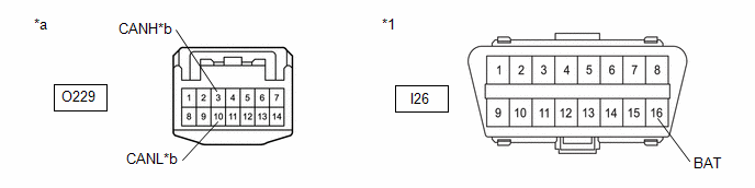
O229-1 (CANH) - I26-16 (BAT) |
Cable disconnected from negative (-) auxiliary battery terminal |
6 kΩ or higher |
|
O229-8 (CANL) - I26-16 (BAT) |
| NG | |
REPAIR OR REPLACE CAN MAIN BUS LINE OR CONNECTOR (NO. 16 GLOBAL CAN JUNCTION CONNECTOR - NO. 13 GLOBAL CAN JUNCTION CONNECTOR) |
|
|
78. |
CHECK FOR SHORT TO +B IN CAN BUS LINE (NO. 16 GLOBAL CAN JUNCTION CONNECTOR - MULTIPLEX NETWORK DOOR ECU) |
(a) Measure the resistance according to the value(s) in the table below.
|
*1 |
DLC3 |
- |
- |
|
*a |
Front view of wire harness connector (to No. 16 Global CAN Junction Connector) |
*b |
to Multiplex Network Door ECU |
Standard Resistance:
|
Tester Connection |
Condition |
Specified Condition |
|---|---|---|
|
O229-5 (CANH) - I26-16 (BAT) |
Cable disconnected from negative (-) auxiliary battery terminal |
6 kΩ or higher |
|
O229-12 (CANL) - I26-16 (BAT) |
| NG | |
GO TO STEP 80 |
|
|
79. |
CHECK FOR SHORT TO +B IN CAN BUS LINE (NO. 16 GLOBAL CAN JUNCTION CONNECTOR - MAIN BODY ECU (MULTIPLEX NETWORK BODY ECU)) |
(a) Measure the resistance according to the value(s) in the table below.
|
*1 |
DLC3 |
- |
- |
|
*a |
Front view of wire harness connector (to No. 16 Global CAN Junction Connector) |
*b |
to Main Body ECU (Multiplex Network Body ECU) |
Standard Resistance:
|
Tester Connection |
Condition |
Specified Condition |
|---|---|---|
|
O229-3 (CANH) - I26-16 (BAT) |
Cable disconnected from negative (-) auxiliary battery terminal |
6 kΩ or higher |
|
O229-10 (CANL) - I26-16 (BAT) |
| OK | |
REPLACE NO. 16 GLOBAL CAN JUNCTION CONNECTOR |
| NG | |
GO TO STEP 81 |
|
80. |
CHECK FOR SHORT TO +B IN CAN BUS LINE (NO. 16 GLOBAL CAN JUNCTION CONNECTOR - MULTIPLEX NETWORK DOOR ECU) |
(a) Disconnect the U39 multiplex network door ECU connector.
(b) Measure the resistance according to the value(s) in the table below.
|
*1 |
DLC3 |
- |
- |
|
*a |
Front view of wire harness connector (to No. 16 Global CAN Junction Connector) |
*b |
to Multiplex Network Door ECU |
Standard Resistance:
|
Tester Connection |
Condition |
Specified Condition |
|---|---|---|
|
O229-5 (CANH) - I26-16 (BAT) |
Cable disconnected from negative (-) auxiliary battery terminal |
6 kΩ or higher |
|
O229-12 (CANL) - I26-16 (BAT) |
| OK | |
REPLACE MULTIPLEX NETWORK DOOR ECU |
| NG | |
REPAIR OR REPLACE CAN BRANCH LINE OR CONNECTOR (NO. 16 GLOBAL CAN JUNCTION CONNECTOR - MULTIPLEX NETWORK DOOR ECU) |
|
81. |
CHECK FOR SHORT TO +B IN CAN BUS LINE (NO. 16 GLOBAL CAN JUNCTION CONNECTOR - MAIN BODY ECU (MULTIPLEX NETWORK BODY ECU)) |
(a) Disconnect the I85 main body ECU (multiplex network body ECU) connector.
(b) Measure the resistance according to the value(s) in the table below.
|
*1 |
DLC3 |
- |
- |
|
*a |
Front view of wire harness connector (to No. 16 Global CAN Junction Connector) |
*b |
to Main Body ECU (Multiplex Network Body ECU) |
Standard Resistance:
|
Tester Connection |
Condition |
Specified Condition |
|---|---|---|
|
O229-3 (CANH) - I26-16 (BAT) |
Cable disconnected from negative (-) auxiliary battery terminal |
6 kΩ or higher |
|
O229-10 (CANL) - I26-16 (BAT) |
| OK | |
REPLACE MAIN BODY ECU (MULTIPLEX NETWORK BODY ECU) |
| NG | |
REPAIR OR REPLACE CAN MAIN BUS LINE OR CONNECTOR (NO. 16 GLOBAL CAN JUNCTION CONNECTOR - MAIN BODY ECU (MULTIPLEX NETWORK BODY ECU)) |
|
82. |
CHECK FOR SHORT TO +B IN CAN BUS LINE (NO. 16 GLOBAL CAN JUNCTION CONNECTOR - NO. 13 GLOBAL CAN JUNCTION CONNECTOR) |
(a) Disconnect the No. 16 global CAN junction connector.
(b) Measure the resistance according to the value(s) in the table below.
|
*1 |
DLC3 |
- |
- |
|
*a |
Front view of wire harness connector (to No. 16 Global CAN Junction Connector) |
*b |
to No. 13 Global CAN Junction Connector |
Standard Resistance:
|
Tester Connection |
Condition |
Specified Condition |
|---|---|---|
|
O233-1 (CANH) - I26-16 (BAT) |
Cable disconnected from negative (-) auxiliary battery terminal |
6 kΩ or higher |
|
O233-12 (CANL) - I26-16 (BAT) |
| NG | |
REPAIR OR REPLACE CAN MAIN BUS LINE OR CONNECTOR (NO. 16 GLOBAL CAN JUNCTION CONNECTOR - NO. 13 GLOBAL CAN JUNCTION CONNECTOR) |
|
|
83. |
CHECK FOR SHORT TO +B IN CAN BUS LINE (NO. 16 GLOBAL CAN JUNCTION CONNECTOR - MAIN BODY ECU (MULTIPLEX NETWORK BODY ECU)) |
(a) Measure the resistance according to the value(s) in the table below.
|
*1 |
DLC3 |
- |
- |
|
*a |
Front view of wire harness connector (to No. 16 Global CAN Junction Connector) |
*b |
to Main Body ECU (Multiplex Network Body ECU) |
Standard Resistance:
|
Tester Connection |
Condition |
Specified Condition |
|---|---|---|
|
O233-2 (CANH) - I26-16 (BAT) |
Cable disconnected from negative (-) auxiliary battery terminal |
6 kΩ or higher |
|
O233-13 (CANL) - I26-16 (BAT) |
| OK | |
REPLACE NO. 16 GLOBAL CAN JUNCTION CONNECTOR |
|
|
84. |
CHECK FOR SHORT TO +B IN CAN BUS LINE (NO. 16 GLOBAL CAN JUNCTION CONNECTOR - MAIN BODY ECU (MULTIPLEX NETWORK BODY ECU)) |
(a) Disconnect the I85 main body ECU (multiplex network body ECU) connector.
(b) Measure the resistance according to the value(s) in the table below.
|
*1 |
DLC3 |
- |
- |
|
*a |
Front view of wire harness connector (to No. 16 Global CAN Junction Connector) |
*b |
to Main Body ECU (Multiplex Network Body ECU) |
Standard Resistance:
|
Tester Connection |
Condition |
Specified Condition |
|---|---|---|
|
O233-2 (CANH) - I26-16 (BAT) |
Cable disconnected from negative (-) auxiliary battery terminal |
6 kΩ or higher |
|
O233-13 (CANL) - I26-16 (BAT) |
| OK | |
REPLACE MAIN BODY ECU (MULTIPLEX NETWORK BODY ECU) |
| NG | |
REPAIR OR REPLACE CAN MAIN BUS LINE OR CONNECTOR (NO. 16 GLOBAL CAN JUNCTION CONNECTOR - MAIN BODY ECU (MULTIPLEX NETWORK BODY ECU)) |
|
85. |
CHECK VEHICLE TYPE |
(a) Check vehicle type.
|
Result |
Proceed to |
|---|---|
|
w/ AFS |
A |
|
w/o AFS |
B |
| B | |
GO TO STEP 108 |
|
|
86. |
CHECK FOR SHORT IN CAN BUS LINES (NO. 20 GLOBAL CAN JUNCTION CONNECTOR - CENTRAL GATEWAY ECU (NETWORK GATEWAY ECU)) |
(a) Disconnect the No. 20 global CAN junction connector.
(b) Measure the resistance according to the value(s) in the table below.
|
*a |
Front view of wire harness connector (to No. 20 Global CAN Junction Connector) |
*b |
to Central Gateway ECU (Network Gateway ECU) |
Standard Resistance:
|
Tester Connection |
Condition |
Specified Condition |
|---|---|---|
|
A197-4 (CANH) - A197-8 (CANL) |
Cable disconnected from negative (-) auxiliary battery terminal |
108 to 132 Ω |
| NG | |
GO TO STEP 90 |
|
|
87. |
CHECK FOR SHORT IN CAN BUS LINES (NO. 20 GLOBAL CAN JUNCTION CONNECTOR - NO. 13 GLOBAL CAN JUNCTION CONNECTOR) |
(a) Measure the resistance according to the value(s) in the table below.
|
*a |
Front view of wire harness connector (to No. 20 Global CAN Junction Connector) |
*b |
to No. 13 Global CAN Junction Connector |
Standard Resistance:
|
Tester Connection |
Condition |
Specified Condition |
|---|---|---|
|
A197-3 (CANH) - A197-7 (CANL) |
Cable disconnected from negative (-) auxiliary battery terminal |
108 to 132 Ω |
| NG | |
GO TO STEP 93 |
|
|
88. |
CHECK FOR SHORT IN CAN BUS LINES (NO. 20 GLOBAL CAN JUNCTION CONNECTOR - HEADLIGHT ECU SUB-ASSEMBLY LH) |
(a) Measure the resistance according to the value(s) in the table below.
|
*a |
Front view of wire harness connector (to No. 20 Global CAN Junction Connector) |
*b |
to Headlight ECU Sub-assembly LH |
Standard Resistance:
|
Tester Connection |
Condition |
Specified Condition |
|---|---|---|
|
A197-1 (CANH) - A197-5 (CANL) |
Cable disconnected from negative (-) auxiliary battery terminal |
200 Ω or higher |
| NG | |
GO TO STEP 91 |
|
|
89. |
CHECK FOR SHORT IN CAN BUS LINES (NO. 20 GLOBAL CAN JUNCTION CONNECTOR - HEADLIGHT ECU SUB-ASSEMBLY RH) |
(a) Measure the resistance according to the value(s) in the table below.
|
*a |
Front view of wire harness connector (to No. 20 Global CAN Junction Connector) |
*b |
to Headlight ECU Sub-assembly RH |
Standard Resistance:
|
Tester Connection |
Condition |
Specified Condition |
|---|---|---|
|
A197-2 (CANH) - A197-6 (CANL) |
Cable disconnected from negative (-) auxiliary battery terminal |
200 Ω or higher |
| OK | |
REPLACE NO. 20 GLOBAL CAN JUNCTION CONNECTOR |
| NG | |
GO TO STEP 92 |
|
90. |
CHECK FOR SHORT IN CAN BUS LINES (NO. 20 GLOBAL CAN JUNCTION CONNECTOR - CENTRAL GATEWAY ECU (NETWORK GATEWAY ECU)) |
(a) Disconnect the I231 central gateway ECU (network gateway ECU) connector.
(b) Measure the resistance according to the value(s) in the table below.
|
*a |
Front view of wire harness connector (to No. 20 Global CAN Junction Connector) |
*b |
to Central Gateway ECU (Network Gateway ECU) |
Standard Resistance:
|
Tester Connection |
Condition |
Specified Condition |
|---|---|---|
|
A197-4 (CANH) - A197-8 (CANL) |
Cable disconnected from negative (-) auxiliary battery terminal |
1 MΩ or higher |
| OK | |
REPLACE CENTRAL GATEWAY ECU (NETWORK GATEWAY ECU) |
| NG | |
REPAIR OR REPLACE CAN MAIN BUS LINES OR CONNECTOR (NO. 20 GLOBAL CAN JUNCTION CONNECTOR - CENTRAL GATEWAY ECU (NETWORK GATEWAY ECU)) |
|
91. |
CHECK FOR SHORT IN CAN BUS LINES (NO. 20 GLOBAL CAN JUNCTION CONNECTOR - HEADLIGHT ECU SUB-ASSEMBLY LH) |
(a) Disconnect the A159 headlight ECU sub-assembly LH connector.
(b) Measure the resistance according to the value(s) in the table below.
|
*a |
Front view of wire harness connector (to No. 20 Global CAN Junction Connector) |
*b |
to Headlight ECU Sub-assembly LH |
Standard Resistance:
|
Tester Connection |
Condition |
Specified Condition |
|---|---|---|
|
A197-1 (CANH) - A197-5 (CANL) |
Cable disconnected from negative (-) auxiliary battery terminal |
1 MΩ or higher |
| OK | |
REPLACE HEADLIGHT ECU SUB-ASSEMBLY LH |
| NG | |
REPAIR OR REPLACE CAN BRANCH LINES OR CONNECTOR (NO. 20 GLOBAL CAN JUNCTION CONNECTOR - HEADLIGHT ECU SUB-ASSEMBLY LH) |
|
92. |
CHECK FOR SHORT IN CAN BUS LINES (NO. 20 GLOBAL CAN JUNCTION CONNECTOR - HEADLIGHT ECU SUB-ASSEMBLY RH) |
(a) Disconnect the A160 headlight ECU sub-assembly RH connector.
(b) Measure the resistance according to the value(s) in the table below.
|
*a |
Front view of wire harness connector (to No. 20 Global CAN Junction Connector) |
*b |
to Headlight ECU Sub-assembly RH |
Standard Resistance:
|
Tester Connection |
Condition |
Specified Condition |
|---|---|---|
|
A197-2 (CANH) - A197-6 (CANL) |
Cable disconnected from negative (-) auxiliary battery terminal |
1 MΩ or higher |
| OK | |
REPLACE HEADLIGHT ECU SUB-ASSEMBLY RH |
| NG | |
REPAIR OR REPLACE CAN BRANCH LINES OR CONNECTOR (NO. 20 GLOBAL CAN JUNCTION CONNECTOR - HEADLIGHT ECU SUB-ASSEMBLY RH) |
|
93. |
CHECK FOR SHORT IN CAN BUS LINES (NO. 13 GLOBAL CAN JUNCTION CONNECTOR - NO. 20 GLOBAL CAN JUNCTION CONNECTOR) |
(a) Reconnect the A197 No. 20 global CAN junction connector.
(b) Disconnect the No. 13 global CAN junction connector.
(c) Measure the resistance according to the value(s) in the table below.
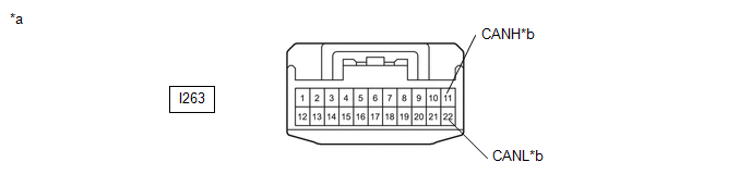
|
*a |
Front view of wire harness connector (to No. 13 Global CAN Junction Connector) |
*b |
to No. 20 Global CAN Junction Connector |
Standard Resistance:
|
Tester Connection |
Condition |
Specified Condition |
|---|---|---|
|
I263-11 (CANH) - I263-22 (CANL) |
Cable disconnected from negative (-) auxiliary battery terminal |
108 to 132 Ω |
| NG | |
REPAIR OR REPLACE CAN MAIN BUS LINES OR CONNECTOR (NO. 13 GLOBAL CAN JUNCTION CONNECTOR - NO. 20 GLOBAL CAN JUNCTION CONNECTOR) |
|
|
94. |
CHECK FOR SHORT IN CAN BUS LINES (NO. 13 GLOBAL CAN JUNCTION CONNECTOR - NO. 16 GLOBAL CAN JUNCTION CONNECTOR) |
(a) Measure the resistance according to the value(s) in the table below.
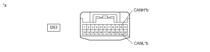
|
*a |
Front view of wire harness connector (to No. 13 Global CAN Junction Connector) |
*b |
to No. 16 Global CAN Junction Connector |
Standard Resistance:
|
Tester Connection |
Condition |
Specified Condition |
|---|---|---|
|
I263-10 (CANH) - I263-21 (CANL) |
Cable disconnected from negative (-) auxiliary battery terminal |
108 to 132 Ω |
| NG | |
GO TO STEP 99 |
|
|
95. |
CHECK FOR SHORT IN CAN BUS LINES (NO. 13 GLOBAL CAN JUNCTION CONNECTOR - CERTIFICATION ECU (SMART KEY ECU ASSEMBLY)) |
(a) Measure the resistance according to the value(s) in the table below.

|
*a |
Front view of wire harness connector (to No. 13 Global CAN Junction Connector) |
*b |
to Certification ECU (Smart Key ECU Assembly) |
Standard Resistance:
|
Tester Connection |
Condition |
Specified Condition |
|---|---|---|
|
I263-7 (CANH) - I263-18 (CANL) |
Cable disconnected from negative (-) auxiliary battery terminal |
200 Ω or higher |
| NG | |
GO TO STEP 97 |
|
|
96. |
CHECK FOR SHORT IN CAN BUS LINES (NO. 13 GLOBAL CAN JUNCTION CONNECTOR - AIR CONDITIONING AMPLIFIER ASSEMBLY) |
(a) Measure the resistance according to the value(s) in the table below.
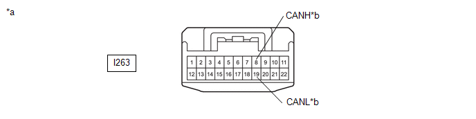
|
*a |
Front view of wire harness connector (to No. 13 Global CAN Junction Connector) |
*b |
to Air Conditioning Amplifier Assembly |
Standard Resistance:
|
Tester Connection |
Condition |
Specified Condition |
|---|---|---|
|
I263-8 (CANH) - I263-19 (CANL) |
Cable disconnected from negative (-) auxiliary battery terminal |
200 Ω or higher |
| OK | |
REPLACE NO. 13 GLOBAL CAN JUNCTION CONNECTOR |
| NG | |
GO TO STEP 98 |
|
97. |
CHECK FOR SHORT IN CAN BUS LINES (NO. 13 GLOBAL CAN JUNCTION CONNECTOR - CERTIFICATION ECU (SMART KEY ECU ASSEMBLY)) |
(a) Disconnect the I222 certification ECU (smart key ECU assembly) connector.
(b) Measure the resistance according to the value(s) in the table below.
|
*a |
Front view of wire harness connector (to No. 13 Global CAN Junction Connector) |
*b |
to Certification ECU (Smart Key ECU Assembly) |
Standard Resistance:
|
Tester Connection |
Condition |
Specified Condition |
|---|---|---|
|
I263-7 (CANH) - I263-18 (CANL) |
Cable disconnected from negative (-) auxiliary battery terminal |
1 MΩ or higher |
| OK | |
REPLACE CERTIFICATION ECU (SMART KEY ECU ASSEMBLY) |
| NG | |
REPAIR OR REPLACE CAN BRANCH LINES OR CONNECTOR (NO. 13 GLOBAL CAN JUNCTION CONNECTOR - CERTIFICATION ECU (SMART KEY ECU ASSEMBLY)) |
|
98. |
CHECK FOR SHORT IN CAN BUS LINES (NO. 13 GLOBAL CAN JUNCTION CONNECTOR - AIR CONDITIONING AMPLIFIER ASSEMBLY) |
(a) Disconnect the I49 air conditioning amplifier assembly connector.
(b) Measure the resistance according to the value(s) in the table below.
|
*a |
Front view of wire harness connector (to No. 13 Global CAN Junction Connector) |
*b |
to Air Conditioning Amplifier Assembly |
Standard Resistance:
|
Tester Connection |
Condition |
Specified Condition |
|---|---|---|
|
I263-8 (CANH) - I263-19 (CANL) |
Cable disconnected from negative (-) auxiliary battery terminal |
1 MΩ or higher |
| OK | |
REPLACE AIR CONDITIONING AMPLIFIER ASSEMBLY |
| NG | |
REPAIR OR REPLACE CAN BRANCH LINES OR CONNECTOR (NO. 13 GLOBAL CAN JUNCTION CONNECTOR - AIR CONDITIONING AMPLIFIER ASSEMBLY) |
|
99. |
CHECK VEHICLE TYPE |
(a) Check vehicle type.
|
Result |
Proceed to |
|---|---|
|
w/ Power Back Door |
A |
|
w/o Power Back Door |
B |
| B | |
GO TO STEP 105 |
|
|
100. |
CHECK FOR SHORT IN CAN BUS LINES (NO. 16 GLOBAL CAN JUNCTION CONNECTOR - NO. 13 GLOBAL CAN JUNCTION CONNECTOR) |
(a) Reconnect the I263 No. 13 global CAN junction connector.
(b) Disconnect the No. 16 global CAN junction connector.
(c) Measure the resistance according to the value(s) in the table below.
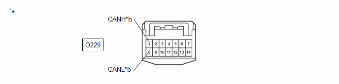
|
*a |
Front view of wire harness connector (to No. 16 Global CAN Junction Connector) |
*b |
to No. 13 Global CAN Junction Connector |
Standard Resistance:
|
Tester Connection |
Condition |
Specified Condition |
|---|---|---|
|
O229-1 (CANH) - O229-8 (CANL) |
Cable disconnected from negative (-) auxiliary battery terminal |
108 to 132 Ω |
| NG | |
REPAIR OR REPLACE CAN MAIN BUS LINES OR CONNECTOR (NO. 16 GLOBAL CAN JUNCTION CONNECTOR - NO. 13 GLOBAL CAN JUNCTION CONNECTOR) |
|
|
101. |
CHECK FOR SHORT IN CAN BUS LINES (NO. 16 GLOBAL CAN JUNCTION CONNECTOR - MULTIPLEX NETWORK DOOR ECU) |
(a) Measure the resistance according to the value(s) in the table below.
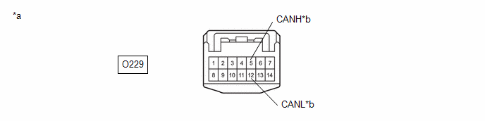
|
*a |
Front view of wire harness connector (to No. 16 Global CAN Junction Connector) |
*b |
to Multiplex Network Door ECU |
Standard Resistance:
|
Tester Connection |
Condition |
Specified Condition |
|---|---|---|
|
O229-5 (CANH) - O229-12 (CANL) |
Cable disconnected from negative (-) auxiliary battery terminal |
200 Ω or higher |
| NG | |
GO TO STEP 103 |
|
|
102. |
CHECK FOR SHORT IN CAN BUS LINES (NO. 16 GLOBAL CAN JUNCTION CONNECTOR - MAIN BODY ECU (MULTIPLEX NETWORK BODY ECU)) |
(a) Measure the resistance according to the value(s) in the table below.
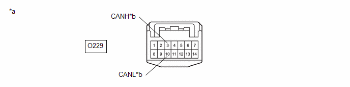
|
*a |
Front view of wire harness connector (to No. 16 Global CAN Junction Connector) |
*b |
to Main Body ECU (Multiplex Network Body ECU) |
Standard Resistance:
|
Tester Connection |
Condition |
Specified Condition |
|---|---|---|
|
O229-3 (CANH) - O229-10 (CANL) |
Cable disconnected from negative (-) auxiliary battery terminal |
108 to 132 Ω |
| OK | |
REPLACE NO. 16 GLOBAL CAN JUNCTION CONNECTOR |
| NG | |
GO TO STEP 104 |
|
103. |
CHECK FOR SHORT IN CAN BUS LINES (NO. 16 GLOBAL CAN JUNCTION CONNECTOR - MULTIPLEX NETWORK DOOR ECU) |
(a) Disconnect the U39 multiplex network door ECU connector.
(b) Measure the resistance according to the value(s) in the table below.
|
*a |
Front view of wire harness connector (to No. 16 Global CAN Junction Connector) |
*b |
to Multiplex Network Door ECU |
Standard Resistance:
|
Tester Connection |
Condition |
Specified Condition |
|---|---|---|
|
O229-5 (CANH) - O229-12 (CANL) |
Cable disconnected from negative (-) auxiliary battery terminal |
1 MΩ or higher |
| OK | |
REPLACE MULTIPLEX NETWORK DOOR ECU |
| NG | |
REPAIR OR REPLACE CAN BRANCH LINES OR CONNECTOR (NO. 16 GLOBAL CAN JUNCTION CONNECTOR - MULTIPLEX NETWORK DOOR ECU) |
|
104. |
CHECK FOR SHORT IN CAN BUS LINES (NO. 16 GLOBAL CAN JUNCTION CONNECTOR - MAIN BODY ECU (MULTIPLEX NETWORK BODY ECU)) |
(a) Disconnect the I85 main body ECU (multiplex network body ECU) connector.
(b) Measure the resistance according to the value(s) in the table below.
|
*a |
Front view of wire harness connector (to No. 16 Global CAN Junction Connector) |
*b |
to Main Body ECU (Multiplex Network Body ECU) |
Standard Resistance:
|
Tester Connection |
Condition |
Specified Condition |
|---|---|---|
|
O229-3 (CANH) - O229-10 (CANL) |
Cable disconnected from negative (-) auxiliary battery terminal |
1 MΩ or higher |
| OK | |
REPLACE MAIN BODY ECU (MULTIPLEX NETWORK BODY ECU) |
| NG | |
REPAIR OR REPLACE CAN MAIN BUS LINES OR CONNECTOR (NO. 16 GLOBAL CAN JUNCTION CONNECTOR - MAIN BODY ECU (MULTIPLEX NETWORK BODY ECU)) |
|
105. |
CHECK FOR SHORT IN CAN BUS LINES (NO. 16 GLOBAL CAN JUNCTION CONNECTOR - NO. 13 GLOBAL CAN JUNCTION CONNECTOR) |
(a) Reconnect the I263 No. 13 global CAN junction connector.
(b) Disconnect the No. 16 global CAN junction connector.
(c) Measure the resistance according to the value(s) in the table below.
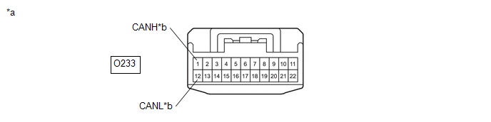
|
*a |
Front view of wire harness connector (to No. 16 Global CAN Junction Connector) |
*b |
to No. 13 Global CAN Junction Connector |
Standard Resistance:
|
Tester Connection |
Condition |
Specified Condition |
|---|---|---|
|
O233-1 (CANH) - O233-12 (CANL) |
Cable disconnected from negative (-) auxiliary battery terminal |
108 to 132 Ω |
| NG | |
REPAIR OR REPLACE CAN MAIN BUS LINES OR CONNECTOR (NO. 16 GLOBAL CAN JUNCTION CONNECTOR - NO. 13 GLOBAL CAN JUNCTION CONNECTOR) |
|
|
106. |
CHECK FOR SHORT IN CAN BUS LINES (NO. 16 GLOBAL CAN JUNCTION CONNECTOR - MAIN BODY ECU (MULTIPLEX NETWORK BODY ECU)) |
(a) Measure the resistance according to the value(s) in the table below.
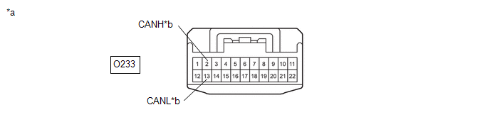
|
*a |
Front view of wire harness connector (to No. 16 Global CAN Junction Connector) |
*b |
to Main Body ECU (Multiplex Network Body ECU) |
Standard Resistance:
|
Tester Connection |
Condition |
Specified Condition |
|---|---|---|
|
O233-2 (CANH) - O233-13 (CANL) |
Cable disconnected from negative (-) auxiliary battery terminal |
108 to 132 Ω |
| OK | |
REPLACE NO. 16 GLOBAL CAN JUNCTION CONNECTOR |
|
|
107. |
CHECK FOR SHORT IN CAN BUS LINES (NO. 16 GLOBAL CAN JUNCTION CONNECTOR - MAIN BODY ECU (MULTIPLEX NETWORK BODY ECU)) |
(a) Disconnect the I85 main body ECU (multiplex network body ECU) connector.
(b) Measure the resistance according to the value(s) in the table below.
|
*a |
Front view of wire harness connector (to No. 16 Global CAN Junction Connector) |
*b |
to Main Body ECU (Multiplex Network Body ECU) |
Standard Resistance:
|
Tester Connection |
Condition |
Specified Condition |
|---|---|---|
|
O233-2 (CANH) - O233-13 (CANL) |
Cable disconnected from negative (-) auxiliary battery terminal |
1 MΩ or higher |
| OK | |
REPLACE MAIN BODY ECU (MULTIPLEX NETWORK BODY ECU) |
| NG | |
REPAIR OR REPLACE CAN MAIN BUS LINES OR CONNECTOR (NO. 16 GLOBAL CAN JUNCTION CONNECTOR - MAIN BODY ECU (MULTIPLEX NETWORK BODY ECU)) |
|
108. |
CHECK FOR SHORT IN CAN BUS LINES (NO. 13 GLOBAL CAN JUNCTION CONNECTOR - CENTRAL GATEWAY ECU (NETWORK GATEWAY ECU)) |
(a) Disconnect the No. 13 global CAN junction connector.
(b) Measure the resistance according to the value(s) in the table below.
|
*a |
Front view of wire harness connector (to No. 13 Global CAN Junction Connector) |
*b |
to Central Gateway ECU (Network Gateway ECU) |
Standard Resistance:
|
Tester Connection |
Condition |
Specified Condition |
|---|---|---|
|
I263-11 (CANH) - I263-22 (CANL) |
Cable disconnected from negative (-) auxiliary battery terminal |
108 to 132 Ω |
| NG | |
GO TO STEP 113 |
|
|
109. |
CHECK FOR SHORT IN CAN BUS LINES (NO. 13 GLOBAL CAN JUNCTION CONNECTOR - NO. 16 GLOBAL CAN JUNCTION CONNECTOR) |
(a) Measure the resistance according to the value(s) in the table below.
|
*a |
Front view of wire harness connector (to No. 13 Global CAN Junction Connector) |
*b |
to No. 16 Global CAN Junction Connector |
Standard Resistance:
|
Tester Connection |
Condition |
Specified Condition |
|---|---|---|
|
I263-10 (CANH) - I263-21 (CANL) |
Cable disconnected from negative (-) auxiliary battery terminal |
108 to 132 Ω |
| NG | |
GO TO STEP 116 |
|
|
110. |
CHECK VEHICLE TYPE |
(a) Check vehicle type.
|
Result |
Proceed to |
|---|---|
|
w/ Smart Key System |
A |
|
w/o Smart Key System |
B |
| B | |
GO TO STEP 112 |
|
|
111. |
CHECK FOR SHORT IN CAN BUS LINES (NO. 13 GLOBAL CAN JUNCTION CONNECTOR - CERTIFICATION ECU (SMART KEY ECU ASSEMBLY)) |
(a) Measure the resistance according to the value(s) in the table below.
|
*a |
Front view of wire harness connector (to No. 13 Global CAN Junction Connector) |
*b |
to Certification ECU (Smart Key ECU Assembly) |
Standard Resistance:
|
Tester Connection |
Condition |
Specified Condition |
|---|---|---|
|
I263-7 (CANH) - I263-18 (CANL) |
Cable disconnected from negative (-) auxiliary battery terminal |
200 Ω or higher |
| NG | |
GO TO STEP 114 |
|
|
112. |
CHECK FOR SHORT IN CAN BUS LINES (NO. 13 GLOBAL CAN JUNCTION CONNECTOR - AIR CONDITIONING AMPLIFIER ASSEMBLY) |
(a) Measure the resistance according to the value(s) in the table below.
|
*a |
Front view of wire harness connector (to No. 13 Global CAN Junction Connector) |
*b |
to Air Conditioning Amplifier Assembly |
Standard Resistance:
|
Tester Connection |
Condition |
Specified Condition |
|---|---|---|
|
I263-8 (CANH) - I263-19 (CANL) |
Cable disconnected from negative (-) auxiliary battery terminal |
200 Ω or higher |
| OK | |
REPLACE NO. 13 GLOBAL CAN JUNCTION CONNECTOR |
| NG | |
GO TO STEP 115 |
|
113. |
CHECK FOR SHORT IN CAN BUS LINES (NO. 13 GLOBAL CAN JUNCTION CONNECTOR - CENTRAL GATEWAY ECU (NETWORK GATEWAY ECU)) |
(a) Disconnect the I231 central gateway ECU (network gateway ECU) connector.
(b) Measure the resistance according to the value(s) in the table below.
|
*a |
Front view of wire harness connector (to No. 13 Global CAN Junction Connector) |
*b |
to Central Gateway ECU (Network Gateway ECU) |
Standard Resistance:
|
Tester Connection |
Condition |
Specified Condition |
|---|---|---|
|
I263-11 (CANH) - I263-22 (CANL) |
Cable disconnected from negative (-) auxiliary battery terminal |
1 MΩ or higher |
| OK | |
REPLACE CENTRAL GATEWAY ECU (NETWORK GATEWAY ECU) |
| NG | |
REPAIR OR REPLACE CAN MAIN BUS LINES OR CONNECTOR (NO. 13 GLOBAL CAN JUNCTION CONNECTOR - CENTRAL GATEWAY ECU (NETWORK GATEWAY ECU)) |
|
114. |
CHECK FOR SHORT IN CAN BUS LINES (NO. 13 GLOBAL CAN JUNCTION CONNECTOR - CERTIFICATION ECU (SMART KEY ECU ASSEMBLY)) |
(a) Disconnect the I222 certification ECU (smart key ECU assembly) connector.
(b) Measure the resistance according to the value(s) in the table below.
|
*a |
Front view of wire harness connector (to No. 13 Global CAN Junction Connector) |
*b |
to Certification ECU (Smart Key ECU Assembly) |
Standard Resistance:
|
Tester Connection |
Condition |
Specified Condition |
|---|---|---|
|
I263-7 (CANH) - I263-18 (CANL) |
Cable disconnected from negative (-) auxiliary battery terminal |
1 MΩ or higher |
| OK | |
REPLACE CERTIFICATION ECU (SMART KEY ECU ASSEMBLY) |
| NG | |
REPAIR OR REPLACE CAN BRANCH LINES OR CONNECTOR (NO. 13 GLOBAL CAN JUNCTION CONNECTOR - CERTIFICATION ECU (SMART KEY ECU ASSEMBLY)) |
|
115. |
CHECK FOR SHORT IN CAN BUS LINES (NO. 13 GLOBAL CAN JUNCTION CONNECTOR - AIR CONDITIONING AMPLIFIER ASSEMBLY) |
(a) Disconnect the I49 air conditioning amplifier assembly connector.
(b) Measure the resistance according to the value(s) in the table below.
|
*a |
Front view of wire harness connector (to No. 13 Global CAN Junction Connector) |
*b |
to Air Conditioning Amplifier Assembly |
Standard Resistance:
|
Tester Connection |
Condition |
Specified Condition |
|---|---|---|
|
I263-8 (CANH) - I263-19 (CANL) |
Cable disconnected from negative (-) auxiliary battery terminal |
1 MΩ or higher |
| OK | |
REPLACE AIR CONDITIONING AMPLIFIER ASSEMBLY |
| NG | |
REPAIR OR REPLACE CAN BRANCH LINES OR CONNECTOR (NO. 13 GLOBAL CAN JUNCTION CONNECTOR - AIR CONDITIONING AMPLIFIER ASSEMBLY) |
|
116. |
CHECK VEHICLE TYPE |
(a) Check vehicle type.
|
Result |
Proceed to |
|---|---|
|
w/ Power Back Door |
A |
|
w/o Power Back Door |
B |
| B | |
GO TO STEP 122 |
|
|
117. |
CHECK FOR SHORT IN CAN BUS LINES (NO. 16 GLOBAL CAN JUNCTION CONNECTOR - NO. 13 GLOBAL CAN JUNCTION CONNECTOR) |
(a) Reconnect the I263 No. 13 global CAN junction connector.
(b) Disconnect the No. 16 global CAN junction connector.
(c) Measure the resistance according to the value(s) in the table below.
|
*a |
Front view of wire harness connector (to No. 16 Global CAN Junction Connector) |
*b |
to No. 13 Global CAN Junction Connector |
Standard Resistance:
|
Tester Connection |
Condition |
Specified Condition |
|---|---|---|
|
O229-1 (CANH) - O229-8 (CANL) |
Cable disconnected from negative (-) auxiliary battery terminal |
108 to 132 Ω |
| NG | |
REPAIR OR REPLACE CAN MAIN BUS LINES OR CONNECTOR (NO. 16 GLOBAL CAN JUNCTION CONNECTOR - NO. 13 GLOBAL CAN JUNCTION CONNECTOR) |
|
|
118. |
CHECK FOR SHORT IN CAN BUS LINES (NO. 16 GLOBAL CAN JUNCTION CONNECTOR - MULTIPLEX NETWORK DOOR ECU) |
(a) Measure the resistance according to the value(s) in the table below.
|
*a |
Front view of wire harness connector (to No. 16 Global CAN Junction Connector) |
*b |
to Multiplex Network Door ECU |
Standard Resistance:
|
Tester Connection |
Condition |
Specified Condition |
|---|---|---|
|
O229-5 (CANH) - O229-12 (CANL) |
Cable disconnected from negative (-) auxiliary battery terminal |
200 Ω or higher |
| NG | |
GO TO STEP 120 |
|
|
119. |
CHECK FOR SHORT IN CAN BUS LINES (NO. 16 GLOBAL CAN JUNCTION CONNECTOR - MAIN BODY ECU (MULTIPLEX NETWORK BODY ECU)) |
(a) Measure the resistance according to the value(s) in the table below.
|
*a |
Front view of wire harness connector (to No. 16 Global CAN Junction Connector) |
*b |
to Main Body ECU (Multiplex Network Body ECU) |
Standard Resistance:
|
Tester Connection |
Condition |
Specified Condition |
|---|---|---|
|
O229-3 (CANH) - O229-10 (CANL) |
Cable disconnected from negative (-) auxiliary battery terminal |
108 to 132 Ω |
| OK | |
REPLACE NO. 16 GLOBAL CAN JUNCTION CONNECTOR |
| NG | |
GO TO STEP 121 |
|
120. |
CHECK FOR SHORT IN CAN BUS LINES (NO. 16 GLOBAL CAN JUNCTION CONNECTOR - MULTIPLEX NETWORK DOOR ECU) |
(a) Disconnect the U39 multiplex network door ECU connector.
(b) Measure the resistance according to the value(s) in the table below.
|
*a |
Front view of wire harness connector (to No. 16 Global CAN Junction Connector) |
*b |
to Multiplex Network Door ECU |
Standard Resistance:
|
Tester Connection |
Condition |
Specified Condition |
|---|---|---|
|
O229-5 (CANH) - O229-12 (CANL) |
Cable disconnected from negative (-) auxiliary battery terminal |
1 MΩ or higher |
| OK | |
REPLACE MULTIPLEX NETWORK DOOR ECU |
| NG | |
REPAIR OR REPLACE CAN BRANCH LINES OR CONNECTOR (NO. 16 GLOBAL CAN JUNCTION CONNECTOR - MULTIPLEX NETWORK DOOR ECU) |
|
121. |
CHECK FOR SHORT IN CAN BUS LINES (NO. 16 GLOBAL CAN JUNCTION CONNECTOR - MAIN BODY ECU (MULTIPLEX NETWORK BODY ECU)) |
(a) Disconnect the I85 main body ECU (multiplex network body ECU) connector.
(b) Measure the resistance according to the value(s) in the table below.
|
*a |
Front view of wire harness connector (to No. 16 Global CAN Junction Connector) |
*b |
to Main Body ECU (Multiplex Network Body ECU) |
Standard Resistance:
|
Tester Connection |
Condition |
Specified Condition |
|---|---|---|
|
O229-3 (CANH) - O229-10 (CANL) |
Cable disconnected from negative (-) auxiliary battery terminal |
1 MΩ or higher |
| OK | |
REPLACE MAIN BODY ECU (MULTIPLEX NETWORK BODY ECU) |
| NG | |
REPAIR OR REPLACE CAN MAIN BUS LINES OR CONNECTOR (NO. 16 GLOBAL CAN JUNCTION CONNECTOR - MAIN BODY ECU (MULTIPLEX NETWORK BODY ECU)) |
|
122. |
CHECK FOR SHORT IN CAN BUS LINES (NO. 16 GLOBAL CAN JUNCTION CONNECTOR - NO. 13 GLOBAL CAN JUNCTION CONNECTOR) |
(a) Reconnect the I263 No. 13 global CAN junction connector.
(b) Disconnect the No. 16 global CAN junction connector.
(c) Measure the resistance according to the value(s) in the table below.
|
*a |
Front view of wire harness connector (to No. 16 Global CAN Junction Connector) |
*b |
to No. 13 Global CAN Junction Connector |
Standard Resistance:
|
Tester Connection |
Condition |
Specified Condition |
|---|---|---|
|
O233-1 (CANH) - O233-12 (CANL) |
Cable disconnected from negative (-) auxiliary battery terminal |
108 to 132 Ω |
| NG | |
REPAIR OR REPLACE CAN MAIN BUS LINES OR CONNECTOR (NO. 16 GLOBAL CAN JUNCTION CONNECTOR - NO. 13 GLOBAL CAN JUNCTION CONNECTOR) |
|
|
123. |
CHECK FOR SHORT IN CAN BUS LINES (NO. 16 GLOBAL CAN JUNCTION CONNECTOR - MAIN BODY ECU (MULTIPLEX NETWORK BODY ECU)) |
(a) Measure the resistance according to the value(s) in the table below.
|
*a |
Front view of wire harness connector (to No. 16 Global CAN Junction Connector) |
*b |
to Main Body ECU (Multiplex Network Body ECU) |
Standard Resistance:
|
Tester Connection |
Condition |
Specified Condition |
|---|---|---|
|
O233-2 (CANH) - O233-13 (CANL) |
Cable disconnected from negative (-) auxiliary battery terminal |
108 to 132 Ω |
| OK | |
REPLACE NO. 16 GLOBAL CAN JUNCTION CONNECTOR |
|
|
124. |
CHECK FOR SHORT IN CAN BUS LINES (NO. 16 GLOBAL CAN JUNCTION CONNECTOR - MAIN BODY ECU (MULTIPLEX NETWORK BODY ECU)) |
(a) Disconnect the I85 main body ECU (multiplex network body ECU) connector.
(b) Measure the resistance according to the value(s) in the table below.
|
*a |
Front view of wire harness connector (to No. 16 Global CAN Junction Connector) |
*b |
to Main Body ECU (Multiplex Network Body ECU) |
Standard Resistance:
|
Tester Connection |
Condition |
Specified Condition |
|---|---|---|
|
O233-2 (CANH) - O233-13 (CANL) |
Cable disconnected from negative (-) auxiliary battery terminal |
1 MΩ or higher |
| OK | |
REPLACE MAIN BODY ECU (MULTIPLEX NETWORK BODY ECU) |
| NG | |
REPAIR OR REPLACE CAN MAIN BUS LINES OR CONNECTOR (NO. 16 GLOBAL CAN JUNCTION CONNECTOR - MAIN BODY ECU (MULTIPLEX NETWORK BODY ECU)) |
|
125. |
CHECK VEHICLE TYPE |
(a) Check vehicle type.
|
Result |
Proceed to |
|---|---|
|
w/ AFS |
A |
|
w/o AFS |
B |
| B | |
GO TO STEP 138 |
|
|
126. |
CHECK FOR OPEN IN CAN MAIN BUS LINES (CENTRAL GATEWAY ECU (NETWORK GATEWAY ECU)) |
(a) Disconnect the central gateway ECU (network gateway ECU) connector.
|
(b) Measure the resistance according to the value(s) in the table below. Standard Resistance:
|
|
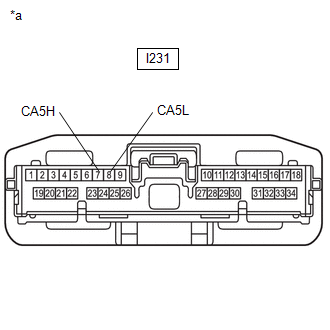
| OK | |
REPLACE CENTRAL GATEWAY ECU (NETWORK GATEWAY ECU) |
|
|
127. |
CHECK FOR OPEN IN CAN MAIN BUS LINES (NO. 20 GLOBAL CAN JUNCTION CONNECTOR - CENTRAL GATEWAY ECU (NETWORK GATEWAY ECU)) |
(a) Reconnect I231 central gateway ECU (network gateway ECU) connector.
(b) Disconnect the No. 20 global CAN junction connector.
(c) Measure the resistance according to the value(s) in the table below.
|
*a |
Front view of wire harness connector (to No. 20 Global CAN Junction Connector) |
*b |
to Central Gateway ECU (Network Gateway ECU) |
Standard Resistance:
|
Tester Connection |
Condition |
Specified Condition |
|---|---|---|
|
A197-4 (CANH) - A197-8 (CANL) |
Cable disconnected from negative (-) auxiliary battery terminal |
108 to 132 Ω |
| NG | |
REPAIR OR REPLACE CAN MAIN BUS LINES OR CONNECTOR (NO. 20 GLOBAL CAN JUNCTION CONNECTOR - CENTRAL GATEWAY ECU (NETWORK GATEWAY ECU)) |
|
|
128. |
CHECK FOR OPEN IN CAN MAIN BUS LINES (NO. 20 GLOBAL CAN JUNCTION CONNECTOR - NO. 13 GLOBAL CAN JUNCTION CONNECTOR) |
(a) Measure the resistance according to the value(s) in the table below.
|
*a |
Front view of wire harness connector (to No. 20 Global CAN Junction Connector) |
*b |
to No. 13 Global CAN Junction Connector |
Standard Resistance:
|
Tester Connection |
Condition |
Specified Condition |
|---|---|---|
|
A197-3 (CANH) - A197-7 (CANL) |
Cable disconnected from negative (-) auxiliary battery terminal |
108 to 132 Ω |
| OK | |
REPLACE NO. 20 GLOBAL CAN JUNCTION CONNECTOR |
|
|
129. |
CHECK FOR OPEN IN CAN MAIN BUS LINES (NO. 13 GLOBAL CAN JUNCTION CONNECTOR - NO. 20 GLOBAL CAN JUNCTION CONNECTOR) |
(a) Reconnect A197 No. 20 global CAN junction connector.
(b) Disconnect the No. 13 global CAN junction connector.
(c) Measure the resistance according to the value(s) in the table below.
|
*a |
Front view of wire harness connector (to No. 13 Global CAN Junction Connector) |
*b |
to No. 20 Global CAN Junction Connector |
Standard Resistance:
|
Tester Connection |
Condition |
Specified Condition |
|---|---|---|
|
I263-11 (CANH) - I263-22 (CANL) |
Cable disconnected from negative (-) auxiliary battery terminal |
108 to 132 Ω |
| NG | |
REPAIR OR REPLACE CAN MAIN BUS LINES OR CONNECTOR (NO. 13 GLOBAL CAN JUNCTION CONNECTOR - NO. 20 GLOBAL CAN JUNCTION CONNECTOR) |
|
|
130. |
CHECK FOR OPEN IN CAN MAIN BUS LINES (NO. 13 GLOBAL CAN JUNCTION CONNECTOR - NO. 16 GLOBAL CAN JUNCTION CONNECTOR) |
(a) Measure the resistance according to the value(s) in the table below.
|
*a |
Front view of wire harness connector (to No. 13 Global CAN Junction Connector) |
*b |
to No. 16 Global CAN Junction Connector |
Standard Resistance:
|
Tester Connection |
Condition |
Specified Condition |
|---|---|---|
|
I263-10 (CANH) - I263-21 (CANL) |
Cable disconnected from negative (-) auxiliary battery terminal |
108 to 132 Ω |
| OK | |
REPLACE NO. 13 GLOBAL CAN JUNCTION CONNECTOR |
|
|
131. |
CHECK VEHICLE TYPE |
(a) Check vehicle type.
|
Result |
Proceed to |
|---|---|
|
w/ Power Back Door |
A |
|
w/o Power Back Door |
B |
| B | |
GO TO STEP 135 |
|
|
132. |
CHECK FOR OPEN IN CAN MAIN BUS LINES (NO. 16 GLOBAL CAN JUNCTION CONNECTOR - NO. 13 GLOBAL CAN JUNCTION CONNECTOR) |
(a) Reconnect the I263 No. 13 global CAN junction connector.
(b) Disconnect the No. 16 global CAN junction connector.
(c) Measure the resistance according to the value(s) in the table below.
|
*a |
Front view of wire harness connector (to No. 16 Global CAN Junction Connector) |
*b |
to No. 13 Global CAN Junction Connector |
Standard Resistance:
|
Tester Connection |
Condition |
Specified Condition |
|---|---|---|
|
O229-1 (CANH) - O229-8 (CANL) |
Cable disconnected from negative (-) auxiliary battery terminal |
108 to 132 Ω |
| NG | |
REPAIR OR REPLACE CAN MAIN BUS LINES OR CONNECTOR (NO. 16 GLOBAL CAN JUNCTION CONNECTOR - NO. 13 GLOBAL CAN JUNCTION CONNECTOR) |
|
|
133. |
CHECK FOR OPEN IN CAN MAIN BUS LINES (NO. 16 GLOBAL CAN JUNCTION CONNECTOR - MAIN BODY ECU (MULTIPLEX NETWORK BODY ECU)) |
(a) Measure the resistance according to the value(s) in the table below.
|
*a |
Front view of wire harness connector (to No. 16 Global CAN Junction Connector) |
*b |
to Main Body ECU (Multiplex Network Body ECU) |
Standard Resistance:
|
Tester Connection |
Condition |
Specified Condition |
|---|---|---|
|
O229-3 (CANH) - O229-10 (CANL) |
Cable disconnected from negative (-) auxiliary battery terminal |
108 to 132 Ω |
| OK | |
REPLACE NO. 16 GLOBAL CAN JUNCTION CONNECTOR |
|
|
134. |
CHECK FOR OPEN IN CAN MAIN BUS LINES (MAIN BODY ECU (MULTIPLEX NETWORK BODY ECU)) |
(a) Reconnect the O229 No. 16 global CAN junction connector.
(b) Disconnect the main body ECU (multiplex network body ECU) connector.
|
(c) Measure the resistance according to the value(s) in the table below. Standard Resistance:
|
|
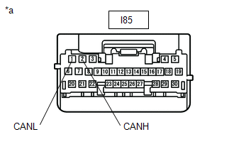
| OK | |
REPLACE MAIN BODY ECU (MULTIPLEX NETWORK BODY ECU) |
| NG | |
REPAIR OR REPLACE CAN MAIN BUS LINES OR CONNECTOR (MAIN BODY ECU (MULTIPLEX NETWORK BODY ECU) - NO. 16 GLOBAL CAN JUNCTION CONNECTOR) |
|
135. |
CHECK FOR OPEN IN CAN MAIN BUS LINES (NO. 16 GLOBAL CAN JUNCTION CONNECTOR - NO. 13 GLOBAL CAN JUNCTION CONNECTOR) |
(a) Reconnect the I263 No. 13 global CAN junction connector.
(b) Disconnect the No. 16 global CAN junction connector.
(c) Measure the resistance according to the value(s) in the table below.
|
*a |
Front view of wire harness connector (to No. 16 Global CAN Junction Connector) |
*b |
to No. 13 Global CAN Junction Connector |
Standard Resistance:
|
Tester Connection |
Condition |
Specified Condition |
|---|---|---|
|
O233-1 (CANH) - O233-12 (CANL) |
Cable disconnected from negative (-) auxiliary battery terminal |
108 to 132 Ω |
| NG | |
REPAIR OR REPLACE CAN MAIN BUS LINES OR CONNECTOR (NO. 16 GLOBAL CAN JUNCTION CONNECTOR - NO. 13 GLOBAL CAN JUNCTION CONNECTOR) |
|
|
136. |
CHECK FOR OPEN IN CAN MAIN BUS LINES (NO. 16 GLOBAL CAN JUNCTION CONNECTOR - MAIN BODY ECU (MULTIPLEX NETWORK BODY ECU)) |
(a) Measure the resistance according to the value(s) in the table below.
|
*a |
Front view of wire harness connector (to No. 16 Global CAN Junction Connector) |
*b |
to Main Body ECU (Multiplex Network Body ECU) |
Standard Resistance:
|
Tester Connection |
Condition |
Specified Condition |
|---|---|---|
|
O233-2 (CANH) - O233-13 (CANL) |
Cable disconnected from negative (-) auxiliary battery terminal |
108 to 132 Ω |
| OK | |
REPLACE NO. 16 GLOBAL CAN JUNCTION CONNECTOR |
|
|
137. |
CHECK FOR OPEN IN CAN MAIN BUS LINES (MAIN BODY ECU (MULTIPLEX NETWORK BODY ECU)) |
(a) Reconnect the O233 No. 16 global CAN junction connector.
(b) Disconnect the main body ECU (multiplex network body ECU) connector.
|
(c) Measure the resistance according to the value(s) in the table below. Standard Resistance:
|
|
| OK | |
REPLACE MAIN BODY ECU (MULTIPLEX NETWORK BODY ECU) |
| NG | |
REPAIR OR REPLACE CAN MAIN BUS LINES OR CONNECTOR (MAIN BODY ECU (MULTIPLEX NETWORK BODY ECU) - NO. 16 GLOBAL CAN JUNCTION CONNECTOR) |
|
138. |
CHECK FOR OPEN IN CAN MAIN BUS LINES (CENTRAL GATEWAY ECU (NETWORK GATEWAY ECU)) |
(a) Disconnect the central gateway ECU (network gateway ECU) connector.
|
(b) Measure the resistance according to the value(s) in the table below. Standard Resistance:
|
|
| OK | |
REPLACE CENTRAL GATEWAY ECU (NETWORK GATEWAY ECU) |
|
|
139. |
CHECK FOR OPEN IN CAN MAIN BUS LINES (NO. 13 GLOBAL CAN JUNCTION CONNECTOR - CENTRAL GATEWAY ECU (NETWORK GATEWAY ECU)) |
(a) Reconnect the I231 central gateway ECU (network gateway ECU) connector.
(b) Disconnect the No. 13 global CAN junction connector.
(c) Measure the resistance according to the value(s) in the table below.
|
*a |
Front view of wire harness connector (to No. 13 Global CAN Junction Connector) |
*b |
to Central Gateway ECU (Network Gateway ECU) |
Standard Resistance:
|
Tester Connection |
Condition |
Specified Condition |
|---|---|---|
|
I263-11 (CANH) - I263-22 (CANL) |
Cable disconnected from negative (-) auxiliary battery terminal |
108 to 132 Ω |
| NG | |
REPAIR OR REPLACE CAN MAIN BUS LINES OR CONNECTOR (NO. 13 GLOBAL CAN JUNCTION CONNECTOR - CENTRAL GATEWAY ECU (NETWORK GATEWAY ECU)) |
|
|
140. |
CHECK FOR OPEN IN CAN MAIN BUS LINES (NO. 13 GLOBAL CAN JUNCTION CONNECTOR - NO. 16 GLOBAL CAN JUNCTION CONNECTOR) |
(a) Measure the resistance according to the value(s) in the table below.
|
*a |
Front view of wire harness connector (to No. 13 Global CAN Junction Connector) |
*b |
to No. 16 Global CAN Junction Connector |
Standard Resistance:
|
Tester Connection |
Condition |
Specified Condition |
|---|---|---|
|
I263-10 (CANH) - I263-21 (CANL) |
Cable disconnected from negative (-) auxiliary battery terminal |
108 to 132 Ω |
| OK | |
REPLACE NO. 13 GLOBAL CAN JUNCTION CONNECTOR |
|
|
141. |
CHECK VEHICLE TYPE |
(a) Check vehicle type.
|
Result |
Proceed to |
|---|---|
|
w/ Power Back Door |
A |
|
w/o Power Back Door |
B |
| B | |
GO TO STEP 145 |
|
|
142. |
CHECK FOR OPEN IN CAN MAIN BUS LINES (NO. 16 GLOBAL CAN JUNCTION CONNECTOR - NO. 13 GLOBAL CAN JUNCTION CONNECTOR) |
(a) Reconnect the I263 No. 13 global CAN junction connector.
(b) Disconnect the No. 16 global CAN junction connector.
(c) Measure the resistance according to the value(s) in the table below.
|
*a |
Front view of wire harness connector (to No. 16 Global CAN Junction Connector) |
*b |
to No. 13 Global CAN Junction Connector |
Standard Resistance:
|
Tester Connection |
Condition |
Specified Condition |
|---|---|---|
|
O229-1 (CANH) - O229-8 (CANL) |
Cable disconnected from negative (-) auxiliary battery terminal |
108 to 132 Ω |
| NG | |
REPAIR OR REPLACE CAN MAIN BUS LINES OR CONNECTOR (NO. 16 GLOBAL CAN JUNCTION CONNECTOR - NO. 13 GLOBAL CAN JUNCTION CONNECTOR) |
|
|
143. |
CHECK FOR OPEN IN CAN MAIN BUS LINES (NO. 16 GLOBAL CAN JUNCTION CONNECTOR - MAIN BODY ECU (MULTIPLEX NETWORK BODY ECU)) |
(a) Measure the resistance according to the value(s) in the table below.
|
*a |
Front view of wire harness connector (to No. 16 Global CAN Junction Connector) |
*b |
to Main Body ECU (Multiplex Network Body ECU) |
Standard Resistance:
|
Tester Connection |
Condition |
Specified Condition |
|---|---|---|
|
O229-3 (CANH) - O229-10 (CANL) |
Cable disconnected from negative (-) auxiliary battery terminal |
108 to 132 Ω |
| OK | |
REPLACE NO. 16 GLOBAL CAN JUNCTION CONNECTOR |
|
|
144. |
CHECK FOR OPEN IN CAN MAIN BUS LINES (MAIN BODY ECU (MULTIPLEX NETWORK BODY ECU)) |
(a) Reconnect the O229 No. 16 global CAN junction connector.
(b) Disconnect the main body ECU (multiplex network body ECU) connector.
|
(c) Measure the resistance according to the value(s) in the table below. Standard Resistance:
|
|
| OK | |
REPLACE MAIN BODY ECU (MULTIPLEX NETWORK BODY ECU) |
| NG | |
REPAIR OR REPLACE CAN MAIN BUS LINES OR CONNECTOR (MAIN BODY ECU (MULTIPLEX NETWORK BODY ECU) - NO. 16 GLOBAL CAN JUNCTION CONNECTOR) |
|
145. |
CHECK FOR OPEN IN CAN MAIN BUS LINES (NO. 16 GLOBAL CAN JUNCTION CONNECTOR - NO. 13 GLOBAL CAN JUNCTION CONNECTOR) |
(a) Reconnect the I263 No. 13 global CAN junction connector.
(b) Disconnect the No. 16 global CAN junction connector.
(c) Measure the resistance according to the value(s) in the table below.
|
*a |
Front view of wire harness connector (to No. 16 Global CAN Junction Connector) |
*b |
to No. 13 Global CAN Junction Connector |
Standard Resistance:
|
Tester Connection |
Condition |
Specified Condition |
|---|---|---|
|
O233-1 (CANH) - O233-12 (CANL) |
Cable disconnected from negative (-) auxiliary battery terminal |
108 to 132 Ω |
| NG | |
REPAIR OR REPLACE CAN MAIN BUS LINES OR CONNECTOR (NO. 16 GLOBAL CAN JUNCTION CONNECTOR - NO. 13 GLOBAL CAN JUNCTION CONNECTOR) |
|
|
146. |
CHECK FOR OPEN IN CAN MAIN BUS LINES (NO. 16 GLOBAL CAN JUNCTION CONNECTOR - MAIN BODY ECU (MULTIPLEX NETWORK BODY ECU)) |
(a) Measure the resistance according to the value(s) in the table below.
|
*a |
Front view of wire harness connector (to No. 16 Global CAN Junction Connector) |
*b |
to Main Body ECU (Multiplex Network Body ECU) |
Standard Resistance:
|
Tester Connection |
Condition |
Specified Condition |
|---|---|---|
|
O233-2 (CANH) - O233-13 (CANL) |
Cable disconnected from negative (-) auxiliary battery terminal |
108 to 132 Ω |
| OK | |
REPLACE NO. 16 GLOBAL CAN JUNCTION CONNECTOR |
|
|
147. |
CHECK FOR OPEN IN CAN MAIN BUS LINES (MAIN BODY ECU (MULTIPLEX NETWORK BODY ECU)) |
(a) Reconnect the O233 No. 16 global CAN junction connector.
(b) Disconnect the main body ECU (multiplex network body ECU) connector.
|
(c) Measure the resistance according to the value(s) in the table below. Standard Resistance:
|
|
| OK | |
REPLACE MAIN BODY ECU (MULTIPLEX NETWORK BODY ECU) |
| NG | |
REPAIR OR REPLACE CAN MAIN BUS LINES OR CONNECTOR (MAIN BODY ECU (MULTIPLEX NETWORK BODY ECU) - NO. 16 GLOBAL CAN JUNCTION CONNECTOR) |


