Toyota Corolla Cross: Camshaft Position Sensor "A" Bank 1 or Single Sensor Circuit Short to Ground (P034011)
DESCRIPTION
The camshaft position sensor (for intake camshaft) (VV1 signal) consists of a magnet and MRE (Magneto Resistance Element).
The intake camshaft has a timing rotor for the camshaft position sensor. When the intake camshaft rotates, changes occur in the air gaps between the timing rotor and MRE, which affects the magnetic field. As a result, the resistance of the MRE material fluctuates. The camshaft position sensor converts the camshaft rotation data to pulse signals, uses the pulse signals. The ECM uses the pulse signals to determine the camshaft angle. Then the ECM uses this data to control fuel injection duration and injection timing.
|
DTC No. | Detection Item |
DTC Detection Condition | Trouble Area |
MIL | Note |
|---|---|---|---|---|---|
|
P034011 | Camshaft Position Sensor "A" Bank 1 or Single Sensor Circuit Short to Ground |
Diagnosis condition:
Abnormal condition:
Malfunction time:
Trip logic:
Detection conditions:
Sensors/components used for detection (Main):
Sensors/components used for detection (Related):
|
| Comes on |
|
- Reference: Inspection using an oscilloscope.
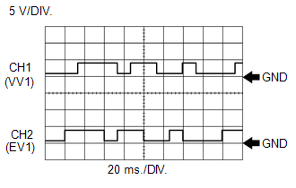
HINT:
- The correct waveform is as shown.
- VV1 stands for the camshaft position sensor signal (for intake camshaft), and EV1 stands for the camshaft position sensor signal (for exhaust camshaft).
ECM Terminal Name
CH1: Between VV1+ and VV1-
CH2: Between EV1+ and EV1-
Tester Range
5 V/DIV., 20 ms./DIV.
Condition
Idling with warm engine
MONITOR DESCRIPTION
2 seconds or more after the ignition switch has been turned ON, if the output voltage of the camshaft position sensor (for intake camshaft) is less than 0.3 V for 4 seconds or more, the ECM determines that the camshaft position sensor (for intake camshaft) circuit is malfunctioning and illuminates the MIL and stores a DTC.
MONITOR STRATEGY
|
Related DTCs | P0342: Camshaft position sensor range check (low voltage) |
|
Required Sensors/Components (Main) | Camshaft position sensor (for intake camshaft) |
|
Required Sensors/Components (Related) |
Crankshaft position sensor |
|
Frequency of Operation | Continuous |
|
Duration | 4 seconds |
|
MIL Operation | Immediate |
|
Sequence of Operation | None |
TYPICAL ENABLING CONDITIONS
|
All of the following conditions are met |
- |
| Starter |
Off |
| Ignition switch |
ON |
| Time after ignition switch off to ON |
2 seconds or more |
|
Auxiliary battery voltage |
8 V or higher |
|
Camshaft position sensor verify pulse input fail (P0340) (Pending / MIL) |
Not detected |
TYPICAL MALFUNCTION THRESHOLDS
|
Camshaft position sensor voltage | Less than 0.3 V |
CONFIRMATION DRIVING PATTERN
HINT:
- After repair has been completed, clear the DTC and then check that the vehicle has returned to normal by performing the following All Readiness check procedure.
Click here
.gif)
- When clearing the permanent DTCs, refer to the "CLEAR PERMANENT DTC" procedure.
Click here
- Connect the GTS to the DLC3.
- Turn the ignition switch to ON.
- Turn the GTS on.
- Clear the DTCs (even if no DTCs are stored, perform the clear DTC procedure).
- Turn the ignition switch off and wait for at least 30 seconds.
- Turn the ignition switch to ON [A].
- Turn the GTS on.
- Wait for 5 seconds or more [B].
- Enter the following menus: Powertrain / Engine / Trouble Codes [C].
- Read the pending DTCs.
HINT:
- If a pending DTC is output, the system is malfunctioning.
- If a pending DTC is not output, perform the following procedure.
- Enter the following menus: Powertrain / Engine / Utility / All Readiness.
- Proceed to the next screen and enter the DTC to be checked.
- Check the DTC judgment result.
GTS Display
Description
NORMAL
- DTC judgment completed
- System normal
ABNORMAL
- DTC judgment completed
- System abnormal
INCOMPLETE
- DTC judgment not completed
- Perform driving pattern after confirming DTC enabling conditions
HINT:
- If the judgment result is NORMAL, the system is normal.
- If the judgment result is ABNORMAL, the system is malfunctioning.
- [A] to [C]: Normal judgment procedure.
The normal judgment procedure is used to complete DTC judgment and also used when clearing permanent DTCs.
- When clearing the permanent DTCs, do not disconnect the cable from the auxiliary battery terminal or attempt to clear the DTCs during this procedure, as doing so will clear the universal trip and normal judgment histories.
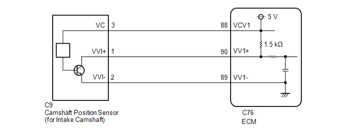
WIRING DIAGRAM
CAUTION / NOTICE / HINT
HINT:
Read Freeze Frame Data using the GTS. The ECM records vehicle and driving condition information as Freeze Frame Data the moment a DTC is stored. When troubleshooting, Freeze Frame Data can help determine if the vehicle was moving or stationary, if the engine was warmed up or not, if the air fuel ratio was lean or rich, and other data from the time the malfunction occurred.
PROCEDURE
| 1. |
CLEAR DTC |
(a) Clear the DTCs.
Powertrain > Engine > Clear DTCs(b) Turn the ignition switch off and wait for at least 30 seconds.
|
.gif)
| 2. |
CHECK DTC OUTPUT (DTC P034011 OR P034015) |
HINT:
Make sure that the connector is properly connected. If it is not, securely connect it and check for DTCs again.
(a) Disconnect the camshaft position sensor (for intake camshaft) connector.
(b) Drive the vehicle in accordance with the driving pattern described in Confirmation Driving Pattern.
(c) Read the DTCs.
Powertrain > Engine > Trouble CodesHINT:
When the ECM, wire harnesses and connectors are normal, DTC P034015 will be stored when the connector of the sensor is disconnected.
|
Result | Proceed to |
|---|---|
|
DTC P034015 is output |
A |
| DTC P034011 is output |
B |
| A |
.gif) | REPLACE CAMSHAFT POSITION SENSOR (FOR INTAKE CAMSHAFT) |
|
| 3. |
CHECK HARNESS AND CONNECTOR (CAMSHAFT POSITION SENSOR (FOR INTAKE CAMSHAFT) - ECM) |
(a) Disconnect the camshaft position sensor (for intake camshaft) connector.
(b) Disconnect the ECM connector.
(c) Measure the resistance according to the value(s) in the table below.
Standard Resistance:
|
Tester Connection | Condition |
Specified Condition |
|---|---|---|
|
C9-1 (VVI+) or C76-90 (VV1+) - Body ground and other terminals |
Always | 10 kΩ or higher |
|
C9-2 (VVI-) or C76-89 (VV1-) - Body ground and other terminals |
Always | 10 kΩ or higher |
| OK | | REPLACE ECM
|
| NG | | REPAIR OR REPLACE HARNESS OR CONNECTOR |
READ NEXT:
 Camshaft Position Sensor "A" Bank 1 or Single Sensor Circuit Short to Battery or Open (P034015)
DESCRIPTION Refer to DTC P034011. Click here
DTC No. Detection Item
DTC Detection Condition Trouble Area
MIL Note
P034015 Camshaft Position Sensor "A" Bank 1 or Sin
Camshaft Position Sensor "A" Bank 1 or Single Sensor No Signal (P034031)
DESCRIPTION Refer to DTC P034011. Click here
DTC No. Detection Item
DTC Detection Condition Trouble Area
MIL Note
P034031 Camshaft Position Sensor "A" Bank 1 or Sin
Camshaft Position Sensor "B" Bank 1 Circuit Short to Ground (P036511)
DESCRIPTION The camshaft position sensor (for exhaust camshaft) (EV1 signal) consists of a magnet and MRE (Magneto Resistance Element).
The exhaust camshaft has a timing rotor for the camshaft posit
SEE MORE:
 Electric Parking Brake Switch Signal Compare Failure (C060962)
DESCRIPTION
When the electric parking brake switch is pulled, a lock request
signal is sent from the skid control ECU (brake actuator assembly) to the parking
brake actuator assembly. When the electric parking brake switch is pushed, a release
request signal is sent from the skid control ECU
Vehicle Behavior Chart
VEHICLE BEHAVIOR CHART VEHICLE BEHAVIOR CHART
(a) Vehicle behavior categorized by DTC If a DTC is output, the vehicle behaves as follows.
DTC No. Detection Item
Vehicle Behavior when DTC is Output
P033506 Crankshaft Position Sensor "A" Algorithm Based Failure
Norm
