Toyota Corolla Cross: Camshaft Position Sensor "A" Bank 1 or Single Sensor No Signal (P034031)
DESCRIPTION
Refer to DTC P034011.
Click here
.gif)
|
DTC No. | Detection Item |
DTC Detection Condition | Trouble Area |
MIL | Note |
|---|---|---|---|---|---|
|
P034031 | Camshaft Position Sensor "A" Bank 1 or Single Sensor No Signal |
Diagnosis condition:
Abnormal condition:
Malfunction time:
Trip logic:
Detection conditions:
Sensors/components used for detection (Main):
Sensors/components used for detection (Related):
|
| Comes on |
|
Reference: Inspection using an oscilloscope.
Click here
MONITOR DESCRIPTION
When the engine is running and no camshaft position sensor (for intake camshaft) signal is received for 5 seconds or more, the ECM determines that the camshaft position sensor (for intake camshaft) circuit is malfunctioning and illuminates the MIL and stores a DTC.
MONITOR STRATEGY
|
Related DTCs | P0340: Camshaft position sensor verify pulse input |
|
Required Sensors/Components (Main) | Camshaft position sensor (for intake camshaft) |
|
Required Sensors/Components (Related) |
Crankshaft position sensor |
|
Frequency of Operation | Continuous |
|
Duration | 5 seconds |
|
MIL Operation | Immediate |
|
Sequence of Operation | None |
TYPICAL ENABLING CONDITIONS
|
All of the following conditions are met |
- |
| Auxiliary battery voltage |
8 V or higher |
| Ignition switch |
ON |
| Camshaft position sensor voltage |
0.3 to 4.7 V |
| Engine speed |
600 rpm or higher |
| Camshaft position sensor range check fail (P0342, P0343) (Pending / MIL) |
Not detected |
TYPICAL MALFUNCTION THRESHOLDS
|
Camshaft position sensor signal | No signal |
CONFIRMATION DRIVING PATTERN
HINT:
- After repair has been completed, clear the DTC and then check that the vehicle has returned to normal by performing the following All Readiness check procedure.
Click here
- When clearing the permanent DTCs, refer to the "CLEAR PERMANENT DTC" procedure.
Click here
- Connect the GTS to the DLC3.
- Turn the ignition switch to ON.
- Turn the GTS on.
- Clear the DTCs (even if no DTCs are stored, perform the clear DTC procedure).
- Turn the ignition switch off and wait for at least 30 seconds.
- Start the engine [A].
- Idle the engine for 10 seconds or more [B].
- Turn the GTS on.
- Enter the following menus: Powertrain / Engine / Trouble Codes [C].
- Read the pending DTCs.
HINT:
- If a pending DTC is output, the system is malfunctioning.
- If a pending DTC is not output, perform the following procedure.
- Enter the following menus: Powertrain / Engine / Utility / All Readiness.
- Proceed to the next screen and enter the DTC to be checked.
- Check the DTC judgment result.
GTS Display
Description
NORMAL
- DTC judgment completed
- System normal
ABNORMAL
- DTC judgment completed
- System abnormal
INCOMPLETE
- DTC judgment not completed
- Perform driving pattern after confirming DTC enabling conditions
HINT:
- If the judgment result is NORMAL, the system is normal.
- If the judgment result is ABNORMAL, the system is malfunctioning.
- If the judgment result is INCOMPLETE, perform steps [B] through [C] again.
- [A] to [C]: Normal judgment procedure.
The normal judgment procedure is used to complete DTC judgment and also used when clearing permanent DTCs.
- When clearing the permanent DTCs, do not disconnect the cable from the auxiliary battery terminal or attempt to clear the DTCs during this procedure, as doing so will clear the universal trip and normal judgment histories.
WIRING DIAGRAM
Refer to DTC P034011.
Click here
CAUTION / NOTICE / HINT
HINT:
- If no problem is found through this diagnostic troubleshooting procedure, there may be a mechanical problem with the engine.
- Read Freeze Frame Data using the GTS. The ECM records vehicle and driving condition information as Freeze Frame Data the moment a DTC is stored. When troubleshooting, Freeze Frame Data can help determine if the vehicle was moving or stationary, if the engine was warmed up or not, if the air fuel ratio was lean or rich, and other data from the time the malfunction occurred.
PROCEDURE
|
1. | CHECK DTC OUTPUT (DTC P034031 AND P034011 OR P034015) |
(a) Read the DTCs.
Powertrain > Engine > Trouble Codes|
Result | Proceed to |
|---|---|
|
DTC P034031 is output |
A |
| DTC P034031 and P034011 or P034015 are output |
B |
HINT:
If DTC P034011 or P034015 is output, perform troubleshooting for it first.
| B |
.gif) | GO TO DTC CHART |
|
.gif)
| 2. |
CHECK TERMINAL VOLTAGE AND INTERNAL RESISTANCE (CAMSHAFT POSITION SENSOR (FOR INTAKE CAMSHAFT) AND ECM) |
|
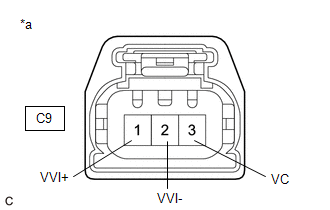
*a | Front view of wire harness connector (to Camshaft Position Sensor (for Intake Camshaft)) |
HINT:
Make sure that the connector is properly connected. If it is not, securely connect it and check for DTCs again.
(a) Disconnect the camshaft position sensor (for intake camshaft) connector.
(b) Turn the ignition switch to ON.
(c) Measure the voltage according to the value(s) in the table below.
Standard Voltage:
|
Tester Connection | Condition |
Specified Condition |
|---|---|---|
|
C9-3 (VC) - Body ground |
Ignition switch ON | 4.5 to 5.5 V |
|
C9-1 (VVI+) - Body ground |
Ignition switch ON | 3.0 to 5.0 V |
(d) Turn the ignition switch off.
(e) Measure the resistance according to the value(s) in the table below.
Standard Resistance:
|
Tester Connection | Condition |
Specified Condition |
|---|---|---|
|
C9-2 (VVI-) - Body ground |
Ignition switch off | Below 1 Ω |
| NG | | GO TO STEP 5 |
|
| 3. |
INSPECT CAMSHAFT POSITION SENSOR (FOR INTAKE CAMSHAFT) |
(a) Remove the camshaft position sensor (for intake camshaft).
Click here
(b) Confirm that there is no oil on the connecting parts of the camshaft position sensor (for intake camshaft) connector.
OK:
There is no oil on the connecting parts of the camshaft position sensor (for intake camshaft) connector.
| NG | | REPLACE CAMSHAFT POSITION SENSOR (FOR INTAKE CAMSHAFT) |
|
| 4. |
INSPECT CAMSHAFT POSITION SENSOR (FOR INTAKE CAMSHAFT) |
|
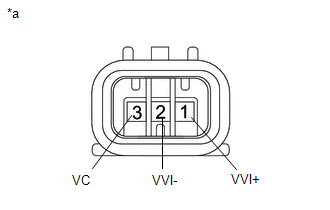
*a | Component without harness connected (Camshaft Position Sensor (for Intake Camshaft)) |
(a) Disconnect the camshaft position sensor (for intake camshaft) connector.
(b) Measure the resistance according to the value(s) in the table below.
Standard Resistance:
|
Tester Connection | Condition |
Specified Condition |
|---|---|---|
|
3 (VC) - 1 (VVI+) | Always |
10 kΩ or higher |
|
3 (VC) - 2 (VVI-) | Always |
10 kΩ or higher |
|
1 (VVI+) - 2 (VVI-) | Always |
10 kΩ or higher |
| OK | | REPLACE ECM
|
| NG | | REPLACE CAMSHAFT POSITION SENSOR (FOR INTAKE CAMSHAFT) |
| 5. |
CHECK HARNESS AND CONNECTOR (CAMSHAFT POSITION SENSOR (FOR INTAKE CAMSHAFT) - ECM) |
(a) Disconnect the camshaft position sensor (for intake camshaft) connector.
(b) Disconnect the ECM connector.
(c) Measure the resistance according to the value(s) in the table below.
Standard Resistance:
|
Tester Connection | Condition |
Specified Condition |
|---|---|---|
|
C9-3 (VC) - C76-88 (VCV1) |
Always | Below 1 Ω |
|
C9-1 (VVI+) - C76-90 (VV1+) |
Always | Below 1 Ω |
|
C9-2 (VVI-) - C76-89 (VV1-) |
Always | Below 1 Ω |
|
C9-3 (VC) or C76-88 (VCV1) - Body ground and other terminals |
Always | 10 kΩ or higher |
|
C9-1 (VVI+) or C76-90 (VV1+) - Body ground and other terminals |
Always | 10 kΩ or higher |
|
C9-2 (VVI-) or C76-89 (VV1-) - Body ground and other terminals |
Always | 10 kΩ or higher |
| OK | | REPLACE ECM
|
| NG | | REPAIR OR REPLACE HARNESS OR CONNECTOR |
READ NEXT:
 Camshaft Position Sensor "B" Bank 1 Circuit Short to Ground (P036511)
DESCRIPTION The camshaft position sensor (for exhaust camshaft) (EV1 signal) consists of a magnet and MRE (Magneto Resistance Element).
The exhaust camshaft has a timing rotor for the camshaft posit
Camshaft Position Sensor "B" Bank 1 Circuit Short to Battery or Open (P036515)
DESCRIPTION Refer to DTC P036511. Click here
DTC No. Detection Item
DTC Detection Condition Trouble Area
MIL Note
P036515 Camshaft Position Sensor "B" Bank 1 Circui
Camshaft Position Sensor "B" Bank 1 Signal Stuck in Range (P03652A)
DESCRIPTION Refer to DTC P036511. Click here
DTC No. Detection Item
DTC Detection Condition Trouble Area
MIL Note
P03652A Camshaft Position Sensor "B" Bank 1 Signal
SEE MORE:
 Communication Error from ECM to VSC Invalid Serial Data Received (P163181)
DESCRIPTION The skid control ECU (brake booster with master cylinder assembly) sends signals such as brake request signals to the hybrid vehicle control ECU. When the hybrid vehicle control ECU detects logic error signals sent from the skid control ECU (brake booster with master cylinder assembly) f
Jam Protection Function Activates During Power Back Door Operation
DESCRIPTION When the jam protection function activates during power back door operation, one of the following may be the cause: 1) improper fit of back door, or a foreign object is stuck in the back door, 2) malfunctioning power back door sensor assembly circuit or 3) malfunctioning multiplex networ
