Toyota Corolla Cross: Before Starting Driving Adjustment
BEFORE STARTING DRIVING ADJUSTMENT
CAUTION / NOTICE / HINT
HINT:
- Purpose of millimeter wave radar beam axis learning
- If the installation position or orientation of the millimeter wave radar sensor is changed due to it being removed and reinstalled or replaced with a new one, or due to the front bumper or radiator grille being replaced, it is necessary for the millimeter wave radar sensor to learn the driving direction of the vehicle in order for each driving support system to operate correctly.
- Vehicle driving direction
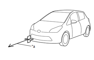
*a
Vehicle driving direction
- Adjustment
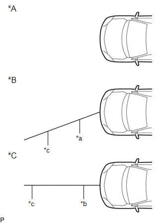
*A
When using a new millimeter wave radar sensor
*B
When reusing millimeter wave radar sensor
*C
Millimeter wave radar sensor after adjustment
*a
Previously learned driving direction
*b
Newly learned driving direction
*c
Horizontal direction
- Adjustment
PROCEDURE
1. PERFORM DRIVING ADJUSTMENT
NOTICE:
- When performing the driving adjustment, obey all applicable traffic laws.
- Select a road where the driving adjustment can be carried out safely.
|
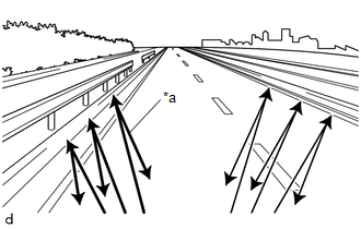
(a) Driving adjustment concept
|
|
(b) Driving conditions
- Drive the vehicle straight ahead at a speed of 30 km/h (19 mph) or more.
- Perform the adjustment outside during daytime, on a sunny or cloudy day.
- If preceding vehicles are present, they should be kept at a distance of at least 20 m (66 ft.)
- There is a stationary object on the roadside such as a guardrail.
- Ensure that there is no snow, ice, or foreign matter on the front or rear of the radar sensor cover or on the front surface of the sensor.
- Make sure that no covers other than the genuine radar sensor cover are installed.
- Drive on a road that does not have heavy snow accumulation around it.
NOTICE:
If the sensor axis is excessively misaligned, the online axis alignment may not be able to make progress.
The total cumulative time that is required for the adjustment to complete when the vehicle is driven with all conditions met is approximately 5 to 15 minutes.
HINT:
- If the adjustment does not complete within a total cumulative time of 15 minutes when the vehicle is driven with all conditions met, perform the adjustment on another route.
- If the adjustment does not complete within a total cumulative time of 30 minutes when the vehicle is driven with all conditions met, perform the adjustment using target recognition.
- If the vehicle is driven unsteadily or many lane changes are performed, the time taken for adjustment to complete may increase.
(c) Road environment
HINT:
When driving on a bumpy or unpaved road, making frequent accelerations and decelerations, etc., the millimeter wave radar sensor assembly condition may be unstable, which may cause adjustment to take a long time.
- Road environments conducive to adjustment
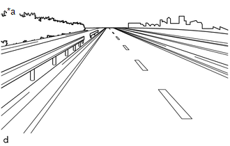
*a
Roads with stationary metallic objects such as guard rails
- Road environments which hinder adjustment
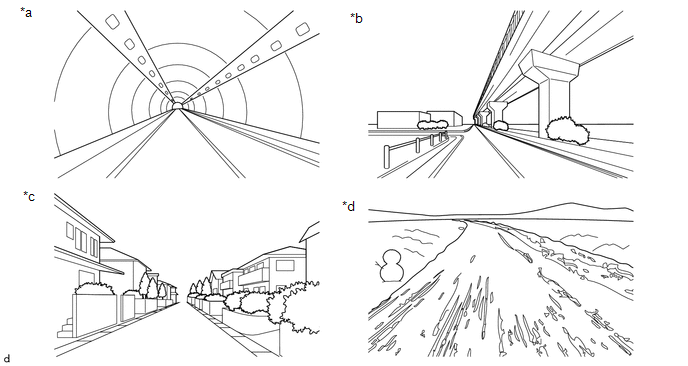
*a
Inside tunnels where there are many diffuse radar reflections
*b
Underneath elevated structures where there are many diffuse radar reflections
*c
In residential neighborhoods where there are many diffuse radar reflections
*d
Snowy roads, dirt roads, etc. where there are very few radar reflections

