Toyota Corolla Cross: A/F (O2) Sensor Positive Current Control Bank 1 Sensor 2 Circuit Short to Ground (P22AB11,P22AB12,P22AB13,P22AB16,P22AB17,P22B211,P22B212)
DESCRIPTION
Refer to DTC P003612.
Click here
.gif)
HINT:
Although the DTC title say O2 sensor, these DTCs relate to the air fuel ratio sensor (sensor 2).
|
DTC No. | Detection Item |
DTC Detection Condition | Trouble Area |
MIL | Note |
|---|---|---|---|---|---|
|
P22AB11 | A/F (O2) Sensor Positive Current Control Bank 1 Sensor 2 Circuit Short to Ground |
The A1B+ voltage is 1.43 V or less for 5 seconds or more (2 trip detection logic). |
| Comes on |
|
| P22AB12 |
A/F (O2) Sensor Positive Current Control Bank 1 Sensor 2 Circuit Short to Battery |
The A1B+ voltage is higher than 6.135 V for 5 seconds or more (2 trip detection logic). |
| Comes on |
|
| P22AB13 |
A/F (O2) Sensor Positive Current Control Bank 1 Sensor 2 Circuit Open |
100 seconds or more elapse after the air fuel ratio sensor (sensor 2) heater turns on and the air fuel ratio sensor (sensor 2) impedance is higher than 510 Ω (2 trip detection logic). |
| Comes on |
|
| P22AB16 |
A/F (O2) Sensor Positive Current Control Bank 1 Sensor 2 Circuit Voltage Below Threshold |
When A1B- voltage is higher than 2.54 V, the difference between terminals A1B+ and A1B- is 0.2 V or less for 5 seconds or more (2 trip detection logic). |
| Comes on |
|
| P22AB17 |
A/F (O2) Sensor Positive Current Control Bank 1 Sensor 2 Circuit Voltage Above Threshold |
Difference between terminals A1B+ and A1B- is higher than 1.71 V for 5 seconds or more (2 trip detection logic). |
| Comes on |
|
| P22B211 |
A/F (O2) Sensor Negative Current Control Bank 1 Sensor 2 Circuit Short to Ground |
The A1B- voltage is 1.07 V or less for 5 seconds or more (2 trip detection logic). |
| Comes on |
|
| P22B212 |
A/F (O2) Sensor Negative Current Control Bank 1 Sensor 2 Circuit Short to Battery |
The A1B- voltage is higher than 4.59 V for 5 seconds or more (2 trip detection logic). |
| Comes on |
|
MONITOR DESCRIPTION
These DTCs are stored when there is an open or short in the air fuel ratio sensor (sensor 2) circuit, or the air fuel ratio sensor (sensor 2) output value is abnormal. The voltage of the air fuel ratio sensor (sensor 2) is monitored while the ignition switch is ON, and the impedance (impedance is an electrical term that indicates the difficulty of flow of current) is checked while engine running. If the voltage of the air fuel ratio sensor (sensor 2) is outside the normal range, or the impedance is outside the normal range, the ECM illuminates the MIL and stores a DTC.
MONITOR STRATEGY
|
Related DTCs | P22AB: Air fuel ratio sensor (sensor 2) circuit open P22AC: Air fuel ratio sensor (sensor 2) range check (A1B+ low voltage) P22AC: Air fuel ratio sensor (sensor 2) correlation (A1B+ and A1B-) P22AD: Air fuel ratio sensor (sensor 2) range check (A1B+ high voltage) P22AD: Air fuel ratio sensor (sensor 2) correlation (A1B+ and A1B-) P22B3: Air fuel ratio sensor (sensor 2) range check (A1B- low voltage) P22B4: Air fuel ratio sensor (sensor 2) range check (A1B- high voltage) |
|
Required Sensors/Components (Main) | Air fuel ratio sensor (sensor 2) |
|
Required Sensors/Components (Related) |
- |
| Frequency of Operation |
Continuous |
| Duration |
5 seconds |
| MIL Operation |
2 driving cycles |
| Sequence of Operation |
None |
TYPICAL ENABLING CONDITIONS
P22AB: Air Fuel Ratio Sensor (Sensor 2) Circuit Open|
Auxiliary battery voltage | 10.5 V or higher |
|
Time after heater on | 100 seconds or more |
|
Ignition switch | ON |
|
Air fuel ratio sensor (sensor 2) heater circuit fail (P0037, P0038, P0057, P0058, P102D, P105D) (Pending / MIL) |
Not detected |
| Air fuel ratio sensor (sensor 2) positive current control circuit range check fail (P22AC, P22AD, P22B9, P22BA) (Pending / MIL) |
Not detected |
|
Air fuel ratio sensor (sensor 2) positive/negative current control circuit correlation fail (P22AC, P22AD, P22B9, P22BA) (Pending / MIL) |
Not detected |
|
Air fuel ratio sensor (sensor 2) negative current control circuit range check fail (P22B3, P22B4, P22C0, P22C1) (Pending / MIL) |
Not detected |
|
Auxiliary battery voltage | 10.5 V or higher |
|
Ignition switch ON | 5 seconds or more |
|
Air fuel ratio sensor (sensor 2) positive current control circuit open fail (P22AB, P22B8) (Pending / MIL) |
Not detected |
| Air fuel ratio sensor (sensor 2) positive/negative current control circuit correlation fail (P22AC, P22AD, P22B9, P22BA) (Pending / MIL) |
Not detected |
|
Air fuel ratio sensor (sensor 2) negative current control circuit range check fail (P22B3, P22B4, P22C0, P22C1) (Pending / MIL) |
Not detected |
|
Auxiliary battery voltage | 10.5 V or higher |
|
Ignition switch ON | 5 seconds or more |
|
A1B- terminal voltage | Higher than 2.54 V |
|
Air fuel ratio sensor (sensor 2) positive current control circuit open fail (P22AB, P22B8) (Pending / MIL) |
Not detected |
| Air fuel ratio sensor (sensor 2) positive current control circuit range check fail (P22AC, P22AD, P22B9, P22BA) (Pending / MIL) |
Not detected |
|
Air fuel ratio sensor (sensor 2) negative current control circuit range check fail (P22B3, P22B4, P22C0, P22C1) (Pending / MIL) |
Not detected |
|
Auxiliary battery voltage | 10.5 V or higher |
|
Ignition switch ON | 5 seconds or more |
|
Air fuel ratio sensor (sensor 2) positive current control circuit open fail (P22AB, P22B8) (Pending / MIL) |
Not detected |
| Air fuel ratio sensor (sensor 2) positive/negative current control circuit correlation fail (P22AC,P22AD,P22B9,P22BA) (Pending / MIL) |
Not detected |
|
Air fuel ratio sensor (sensor 2) positive current control circuit range check fail (P22AC, P22AD, P22B9, P22BA) (Pending / MIL) |
Not detected |
TYPICAL MALFUNCTION THRESHOLDS
P22AB: Air Fuel Ratio Sensor (Sensor 2) Circuit Open|
Air fuel ratio sensor (sensor 2) impedance | Higher than 510 Ω |
|
A1B+ terminal voltage | 1.43 V or less |
|
Difference between A1B+ and A1B- terminal voltage |
0.2 V or less |
|
A1B+ terminal voltage | Higher than 6.135 V |
|
Difference between A1B+ and A1B- terminal voltage |
Higher than 1.71 V |
|
A1B- terminal voltage | 1.07 V or less |
|
A1B- terminal voltage | Higher than 4.59 V |
CONFIRMATION DRIVING PATTERN
HINT:
- After repair has been completed, clear the DTC and then check that the vehicle has returned to normal by performing the following All Readiness check procedure.
Click here
- When clearing the permanent DTCs, refer to the "CLEAR PERMANENT DTC" procedure.
Click here
- Connect the GTS to the DLC3.
- Turn the ignition switch to ON.
- Turn the GTS on.
- Clear the DTCs (even if no DTCs are stored, perform the clear DTC procedure).
- Turn the ignition switch off and wait for at least 30 seconds.
- Start the engine and wait 5 minutes or more [A].
- Turn the GTS on.
- Enter the following menus: Powertrain / Engine / Trouble Codes [B].
- Read the pending DTCs.
HINT:
- If a pending DTC is output, the system is malfunctioning.
- If a pending DTC is not output, perform the following procedure.
- Enter the following menus: Powertrain / Engine / Utility / All Readiness.
- Input the DTC: P22AB11, P22AB12, P22AB13, P22AB16, P22AB17, P22B211 or P22B212.
- Check the DTC judgment result.
GTS Display
Description
NORMAL
- DTC judgment completed
- System normal
ABNORMAL
- DTC judgment completed
- System abnormal
INCOMPLETE
- DTC judgment not completed
- Perform driving pattern after confirming DTC enabling conditions
HINT:
- If the judgment result is NORMAL, the system is normal.
- If the judgment result is ABNORMAL, the system is malfunctioning.
- If the judgment result is INCOMPLETE, idle the engine for 5 minutes and check the DTC judgment result again.
- [A] to [B]: Normal judgment procedure.
The normal judgment procedure is used to complete DTC judgment and also used when clearing permanent DTCs.
- When clearing the permanent DTCs, do not disconnect the cable from the auxiliary battery terminal or attempt to clear the DTCs during this procedure, as doing so will clear the universal trip and normal judgment histories.
WIRING DIAGRAM
Refer to DTC P003612.
Click here
CAUTION / NOTICE / HINT
NOTICE:
Inspect the fuses for circuits related to this system before performing the following procedure.
HINT:
- Sensor 1 refers to the sensor closest to the engine assembly.
- Sensor 2 refers to the sensor farthest away from the engine assembly.
- Refer to "Data List / Active Test" [A/F (O2) Sensor Current B1S2].
Click here
- Read Freeze Frame Data using the GTS. The ECM records vehicle and driving condition information as Freeze Frame Data the moment a DTC is stored. When troubleshooting, Freeze Frame Data can help determine if the vehicle was moving or stationary, if the engine was warmed up or not, if the air fuel ratio was lean or rich, and other data from the time the malfunction occurred.
PROCEDURE
|
1. | CHECK TERMINAL VOLTAGE (AIR FUEL RATIO SENSOR (SENSOR 2) VOLTAGE) |
|
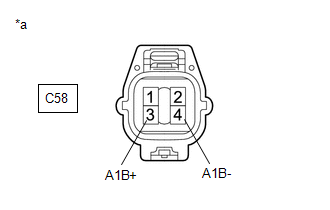
*a | Front view of wire harness connector (to Air Fuel Ratio Sensor (Sensor 2)) |
HINT:
Make sure that the connector is properly connected. If it is not, securely connect it and check for DTCs again.
(a) Disconnect the air fuel ratio sensor (sensor 2) connector.
(b) Turn the ignition switch to ON.
(c) Measure the voltage according to the value(s) in the table below.
Standard Voltage:
|
Tester Connection | Condition |
Specified Condition |
|---|---|---|
|
C58-3 (A1B+) - Body ground |
Ignition switch ON | 2.8 to 3.2 V |
|
C58-4 (A1B-) - Body ground |
Ignition switch ON | 2.3 to 2.7 V |
|
C58-3 (A1B+) - C58-4 (A1B-) |
Ignition switch ON | 0.1 to 0.9 V |
HINT:
Perform "Inspection After Repair" after replacing the air fuel ratio sensor (sensor 2).
Click here
| OK | .gif) | REPLACE AIR FUEL RATIO SENSOR (SENSOR 2) |
|
.gif)
| 2. |
CHECK HARNESS AND CONNECTOR (AIR FUEL RATIO SENSOR (SENSOR 2) - ECM) |
(a) Disconnect the air fuel ratio sensor (sensor 2) connector.
(b) Disconnect the ECM connector.
(c) Measure the resistance according to the value(s) in the table below.
Standard Resistance:
|
Tester Connection | Condition |
Specified Condition |
|---|---|---|
|
C58-1 (HA1B) - C76-8 (HA1B) |
Always | Below 1 Ω |
|
C58-3 (A1B+) - C76-118 (A1B+) |
Always | Below 1 Ω |
|
C58-4 (A1B-) - C76-117 (A1B-) |
Always | Below 1 Ω |
|
C58-1 (HA1B) or C76-8 (HA1B) - Body ground and other terminals |
Always | 10 kΩ or higher |
|
C58-3 (A1B+) or C76-118 (A1B+) - Body ground and other terminals |
Always | 10 kΩ or higher |
|
C58-4 (A1B-) or C76-117 (A1B-) - Body ground and other terminals |
Always | 10 kΩ or higher |
| OK | | REPLACE ECM
|
| NG | | REPAIR OR REPLACE HARNESS OR CONNECTOR |
READ NEXT:
 Evaporative Emission System Switching Valve Control Circuit Actuator Stuck Off (P24187F)
DTC SUMMARY
DTC No. Detection Item
DTC Detection Condition Trouble Area
MIL Note
P24187F Evaporative Emission System Switching Valve Control Circuit Actuator Stuck Off
Ignition Switch On/Start Position Circuit Low Circuit Short to Ground or Open (P253314)
DESCRIPTION When the ignition switch is turned to ON, the auxiliary battery power source is supplied to the IGP and IGR terminals of the ECM. When the ignition switch is off, the auxiliary battery pow
ECM/PCM Engine Off Timer Performance Signal Invalid (P261029,P261093)
DTC SUMMARY
DTC No. Detection Item
DTC Detection Condition Trouble Area
MIL Note
P261029 ECM/PCM Engine Off Timer Performance Signal Invalid
ECM internal malfunct
SEE MORE:
 Battery ECU Communication Stop Mode
DESCRIPTION
Detection Item
Symptom
Trouble Area
Battery ECU Communication Stop Mode
Communication stop for "HV Battery" is indicated on the "Communication
Bus Check" screen of the GTS.
Click here
Changing the vehicle-to-vehicle distance
Each time the switch is pressed, the vehicle-to-vehicle distance setting
will change as follows:
If a preceding vehicle is detected, the preceding vehicle mark will be
displayed.
The actual vehicle-to-vehicle distance varies in accordance with the vehicle
speed. Also, when the vehicle is stopped
