Toyota Corolla Cross: VEHICLE CONTROL HISTORY (RoB)
VEHICLE CONTROL HISTORY (RoB)
DESCRIPTION
- Vehicle Control History (RoB) is a function that captures and stores ECU data when triggered by specific vehicle behavior.
- If the customer states that there was a problem such as the engine not restarting after having been stopped by the stop and start system, it may be possible to diagnose the cause of the malfunction by checking the vehicle history information and freeze frame data.
PRECAUTIONS
- As Vehicle Control History (RoB) may be overwritten whenever the trigger conditions are met, make sure to save Vehicle Control History (RoB) before performing any inspections.
- As Vehicle Control History (RoB) may be stored when performing an Active Test, learning, etc., make sure to clear the Vehicle Control History (RoB) before returning the vehicle to the customer.
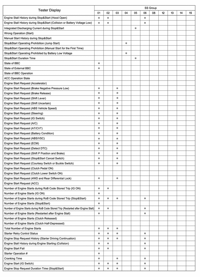
CHECK VEHICLE CONTROL HISTORY (RoB) (STOP AND START SYSTEM)
(a) Enter the following menus.
Powertrain > Stop and Start > Utility|
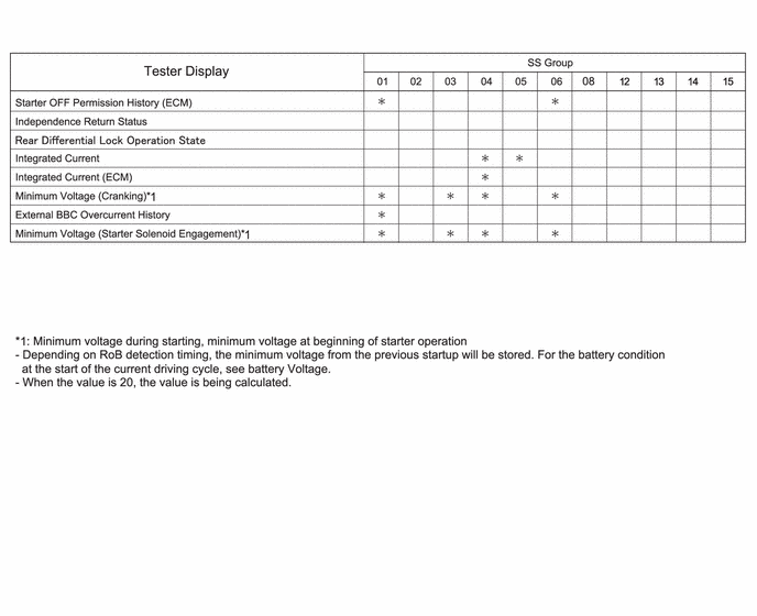
Tester Display |
|---|
| Vehicle Control History (RoB) |
|
Code | Tester Display |
Trigger Description | Stored Group |
Reference Inspection Procedure |
Link |
|---|---|---|---|---|---|
| X0870 |
Stop&Start Prohibition (Power Management) |
- | 04 |
- | - |
|
X0871 | Stop&Start Restart (Power Management) |
- | 05 |
- | - |
|
X0872 | Stop&Start Restart Failure (Engine Restart) |
| 01 |
Proceed to "After Engine Stops due to Stop and Start System, Engine does not Restart" in Problem Symptoms Table |
|
|
X0873 | Hood Open during Stop&Start (Engine Stall) |
While engine was stopped by stop and start system, the hood was opened, causing an engine stall. |
02 | Proceed to "Caused by Hood" troubleshooting procedure of "After Engine Stops due to Stop and Start System, Engine does not Restart" in Problem Symptoms Table |
|
|
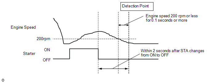
X0874 | Stop&Start Restart Failure (Engine Restart after Engine Stall) |
In a situation where engine is restarting after a failed start by the stop and start system, within 2 seconds after STA changes from ON to OFF, engine speed is 200 rpm or less for 0.1 seconds or more. |
06 | Proceed to "Failure to Restart from IG-ON Engine Stall" in Problem Symptoms Table |
|
|
X0875 | Voltage Low for Stop&Start Control Module (Engine Start from Stop&Start) |
| 03 |
- | - |
|
X0877 | Life Cycle of Starter |
The number of starter operations reaches the specified limit. |
08 | Proceed to "Stop and Start System does not Operate" in Problem Symptoms Table |
|
|
X0879 | Charging Control Malfunction History (EFI) |
| 08 |
Proceed to "Stop and Start System does not Operate" in Problem Symptoms Table |
|
| XF01B |
ECU Security Key Not Registered |
ECU security key not updated |
- | Proceed to "Update ECU Security Key" in Problem Symptoms Table |
|
|
X250C | Air Conditioner System Malfunction |
A stop and start system prohibit request or start request that exceeds the specified range is received from the air conditioning amplifier assembly |
12 | Proceed to "HOW TO PROCEED WITH TROUBLESHOOTING" in Air Conditioning System |
|
| X250D |
Adaptive Cruise Control System Malfunction |
When the vehicle is being driven at 10 km/h (6 mph) or more, a stop and start cancellation request from the dynamic radar cruise control (w/ Full Speed Range Following Function) continues for 3 seconds or more |
13 | Proceed to "After Engine Stops due to Stop and Start System, Engine does not Restart" in Problem Symptoms Table |
|
|
X250E | Parking Support Brake System Malfunction |
When the vehicle is being driven at 30 km/h (19 mph) or more, the parking support brake system control status continues for 3 seconds or more |
14 | Proceed to "HOW TO PROCEED WITH TROUBLESHOOTING" in Parking Support Brake System |
|
|
X250F | Intelligent Parking Assist System Malfunction |
When the vehicle is being driven at 30 km/h (19 mph) or more, the advanced park control status continues for 3 seconds or more |
15 | Proceed to "HOW TO PROCEED WITH TROUBLESHOOTING" in Advanced Park |
|
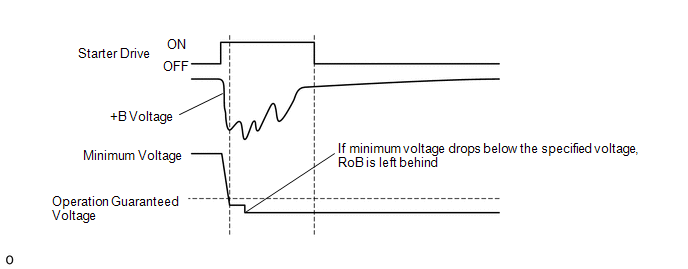
.gif)
 Judgment Region for Voltage Drop When Restarting from Stop and Start (X0875)
HINT:
- When the engine is restarted by the stop and start system, if there is only slight voltage depression of the auxiliary battery and the engine speed does not reach the level at which a complete combustion judgment is made, there may be a malfunction in the starting circuit system. (Figure 1)
- When the engine is restarted by the stop and start system, if there is significant voltage depression of the auxiliary battery and the engine speed does not increase to 200 rpm, starter lock should be considered. (Figure 2)
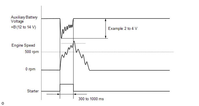
- When the engine is restarted by the stop and start system, if there is significant voltage depression of the auxiliary battery and initial combustion does not occur during starter driven revolution, engine control factors (injector system, ignition system, STA input open circuit, etc.) should be considered. (Figure 3)
- When the engine is restarted by the stop and start system, if there is significant voltage depression of the auxiliary battery and engine stall occurs after the engine speed reaches the level at which a complete combustion judgment is made, engine control factors (accumulated deposits, fuel system, etc.) should be considered. (Figure 4)
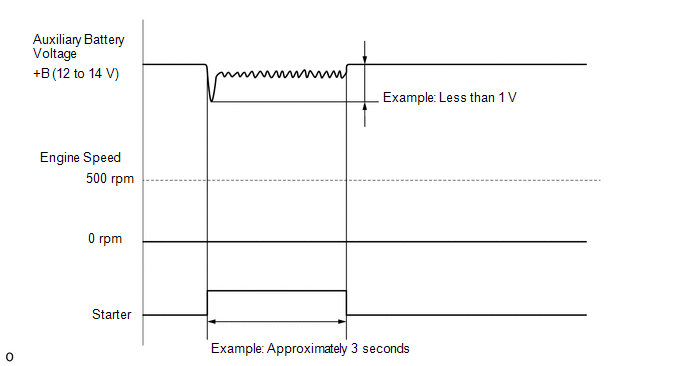 FIGURE 2
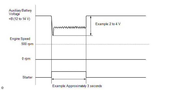 FIGURE 3
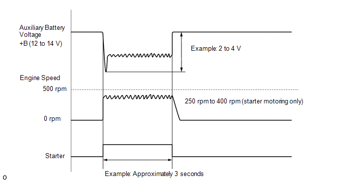 FIGURE 4
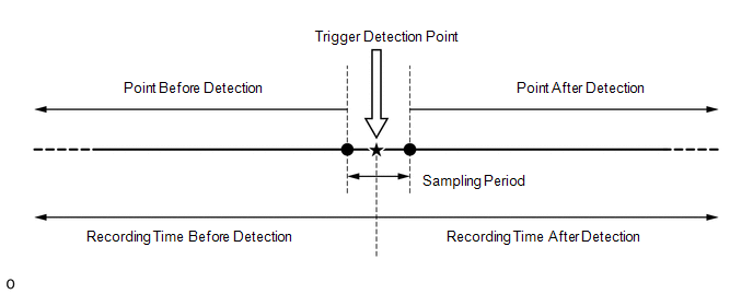
 Stored Data
 |
Stored Group | Number of Records |
Number of Multi Freeze Frame Data Points |
Multi Freeze Frame Data Sampling Period |
Note |
|---|---|---|---|---|
| 01 |
2 codes HINT:
| 7 points (1 point at detection + 5 points before detection + 1 point after detection) |
0.5 seconds | The data can be cleared using the GTS. |
|
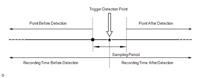
02 | 1 code HINT:
| 3 points (1 point at detection + 1 point before detection + 1 point after detection) |
0.5 seconds | The data can be cleared using the GTS. |
|
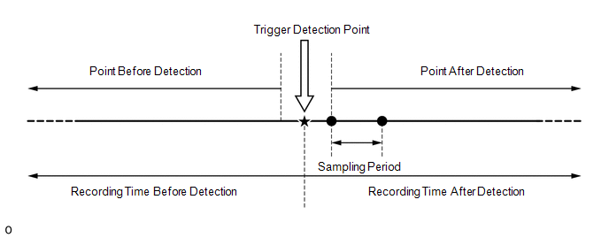
03 | 2 codes HINT:
| 3 points (1 point at detection 0 point before detection +2 point after detection) |
0.5 seconds | The data can be cleared using the GTS. |
|
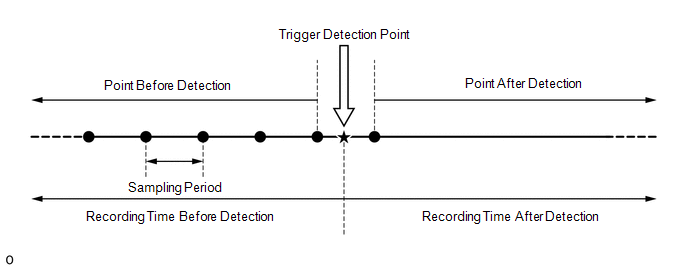
04 | 8 codes HINT:
| 2 points (1 point at detection + 1 point before detection + 0 points after detection) |
1.0 seconds | The data can be cleared using the GTS. |
|
05 | 8 codes HINT:
| 2 points (1 point at detection + 1 point before detection + 0 points after detection) |
1.0 seconds | The data can be cleared using the GTS. |
|
06 | 1 code HINT:
| 7 points (1 point at detection + 5 points before detection + 1 point after detection) |
0.5 seconds | The data can be cleared using the GTS. |
|
08 | 1 code HINT: Once detected, the latest data is not stored until the data is cleared. |
1 point (multi freeze frame data not available) |
- | The data can be cleared using the GTS. |
|
12 | 2 code HINT:
| 1 point (multi Freeze Frame Data not available) |
- | The data cannot be cleared using the GTS. |
|
13 | 1 code HINT:
| 1 point (multi Freeze Frame Data not available) |
- | The data can be cleared using the GTS. |
|
14 | 1 code HINT:
| 1 point (multi Freeze Frame Data not available) |
- | The data can be cleared using the GTS. |
|
15 | 1 code HINT:
| 1 point (multi Freeze Frame Data not available) |
- | The data can be cleared using the GTS. |
HINT:
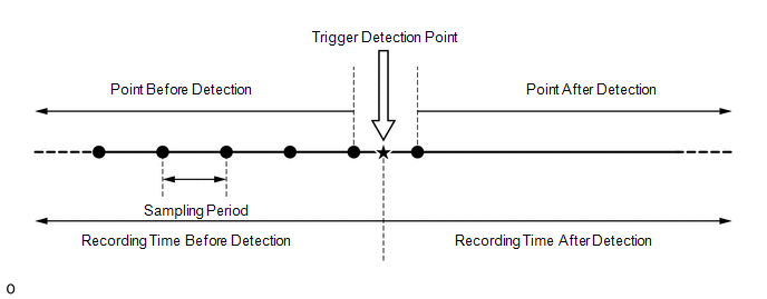
- The multi freeze frame data makes it possible to check the engine status (ECU data) before and after the trigger point at which the vehicle control history (RoB) was stored.
- The number of stored points differs according to the stored group.
- If the value of a data item does not change across the freeze frame data points, only the value from the detection point at which the vehicle control history (RoB) was stored will be displayed.
 Stored Group 02
 Stored Group 03
 Stored Group 04
 Stored Group 05
Stored Group 06
Stored Group 05
Stored Group 06
Only 1 measurement point can be displayed for stored group 08, 12, 13, 14 or 15 Freeze Frame Data.
CLEAR VEHICLE CONTROL HISTORY (RoB) (STOP AND START SYSTEM)
(a) Enter the following menus.
Powertrain > Stop and Start > Utility|
Tester Display |
|---|
| Vehicle Control History (RoB) |
(b) Select the name of a vehicle control history (RoB) item to display the data from the time of control.
(c) Check the output data.
Vehicle Control History (RoB) Data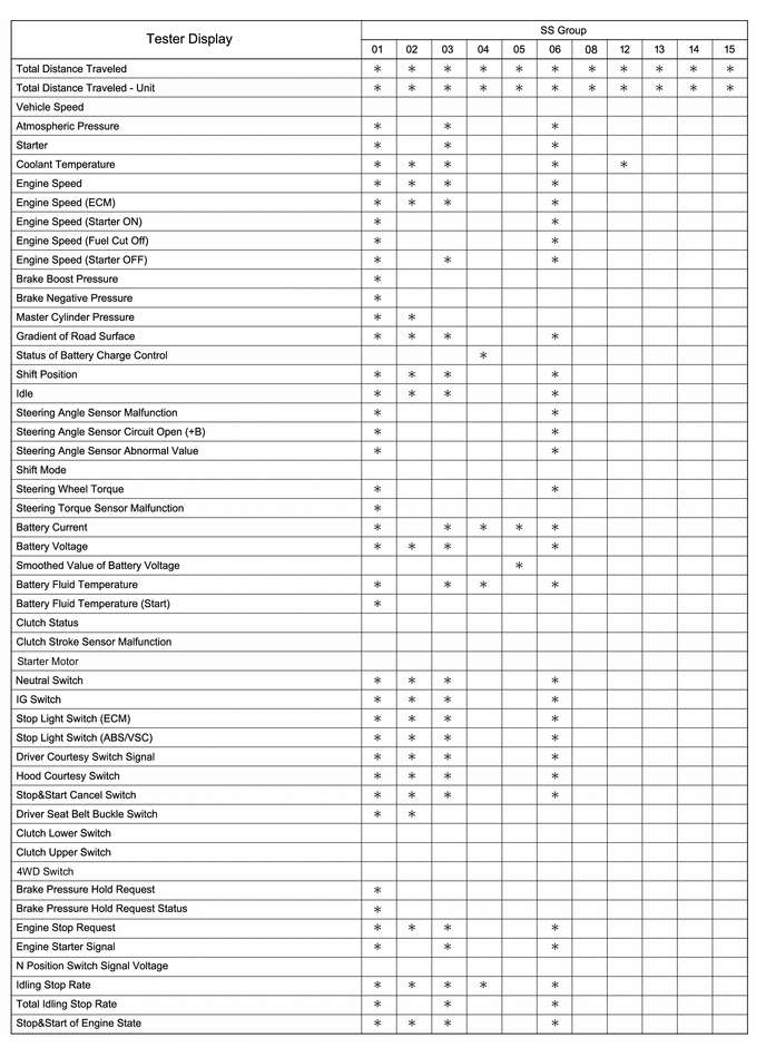 Vehicle Control History (RoB) Data
 Vehicle Control History (RoB) Data