Toyota Corolla Cross: Throttle/Pedal Position Sensor/Switch "E" Circuit Short to Battery (P212512)
DESCRIPTION
HINT:
These DTCs relate to the accelerator pedal position sensor.
Refer to DTC P212012.
Click here .gif)
|
DTC No. | Detection Item |
DTC Detection Condition | Trouble Area |
MIL | Note |
|---|---|---|---|---|---|
|
P212512 | Throttle/Pedal Position Sensor/Switch "E" Circuit Short to Battery |
Diagnosis condition:
Abnormal condition:
Malfunction time:
Trip logic:
Detection conditions:
Sensors/components used for detection:
|
| Comes on |
|
MONITOR DESCRIPTION
When the ignition switch is turned ON, the voltage of VPA is between 0.4 V and 3.45 V and the voltage of VPA2 is 4.8 V or more for 2 seconds or more, the ECM determines that the accelerator pedal sensor assembly circuit is malfunctioning and illuminates the MIL and stores a DTC.
MONITOR STRATEGY
|
Related DTCs | P2128: Accelerator pedal position sensor 2 range check (high voltage) |
|
Required Sensors/Components (Main) | Accelerator pedal sensor assembly |
|
Required Sensors/Components (Related) |
- |
| Frequency of Operation |
Continuous |
| Duration |
2.0 seconds |
| MIL Operation |
Immediate |
| Sequence of Operation |
None |
TYPICAL ENABLING CONDITIONS
|
Monitor runs whenever the following DTCs are not stored |
None |
TYPICAL MALFUNCTION THRESHOLDS
|
VPA2 voltage when VPA voltage 0.4 to 3.45 V |
4.8 V or higher |
CONFIRMATION DRIVING PATTERN
Refer to DTC P212012.
Click here
FAIL-SAFE
When these DTCs are stored, the ECM enters fail-safe mode. If either of the 2 sensor circuits malfunctions, the ECM limits the engine output. If both of the circuits malfunction, the ECM regards the accelerator pedal as being released. As a result, the throttle valve is closed and the engine idles.
Fail-safe mode continues until a pass condition is detected, and the ignition switch is turned off.
WIRING DIAGRAM
Refer to DTC P212012.
Click here
CAUTION / NOTICE / HINT
HINT:
Read Freeze Frame Data using the GTS. The ECM records vehicle and driving condition information as Freeze Frame Data the moment a DTC is stored. When troubleshooting, Freeze Frame Data can help determine if the vehicle was moving or stationary, if the engine was warmed up or not, if the air fuel ratio was lean or rich, and other data from the time the malfunction occurred.
PROCEDURE
| 1. |
CHECK TERMINAL VOLTAGE (ACCELERATOR PEDAL SENSOR ASSEMBLY) |
|
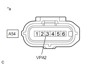
*a | Front view of wire harness connector (to Accelerator Pedal Sensor Assembly) |
HINT:
Make sure that the connector is properly connected. If it is not, securely connect it and check for DTCs again.
(a) Disconnect the accelerator pedal sensor assembly connector.
(b) Turn the ignition switch to ON.
(c) Measure the voltage according to the value(s) in the table below.
Standard Voltage:
|
Tester Connection | Condition |
Specified Condition |
|---|---|---|
|
A54-3 (VPA2) - Body ground |
Ignition switch ON | Below 1 V |
HINT:
If the value differs from standard, there may be a short in the power source circuit.
| NG | .gif) | GO TO STEP 4 |
|
.gif)
| 2. |
CHECK HARNESS AND CONNECTOR (ACCELERATOR PEDAL SENSOR ASSEMBLY - BODY GROUND) |
(a) Disconnect the accelerator pedal sensor assembly connector.
(b) Measure the resistance according to the value(s) in the table below.
Standard Resistance:
|
Tester Connection | Condition |
Specified Condition |
|---|---|---|
|
A54-2 (EPA2) - Body ground |
Always | Below 1 Ω |
| OK | | REPLACE ACCELERATOR PEDAL SENSOR ASSEMBLY |
|
| 3. |
CHECK HARNESS AND CONNECTOR (ACCELERATOR PEDAL SENSOR ASSEMBLY - ECM) |
(a) Disconnect the accelerator pedal sensor assembly connector.
(b) Disconnect the ECM connector.
(c) Measure the resistance according to the value(s) in the table below.
Standard Resistance:
|
Tester Connection | Condition |
Specified Condition |
|---|---|---|
|
A54-2 (EPA2) - A47-59 (EPA2) |
Always | Below 1 Ω |
| OK | | REPLACE ECM
|
| NG | | REPAIR OR REPLACE HARNESS OR CONNECTOR |
| 4. |
CHECK HARNESS AND CONNECTOR (ACCELERATOR PEDAL SENSOR ASSEMBLY - ECM) |
(a) Disconnect the accelerator pedal sensor assembly connector.
(b) Disconnect the ECM connector.
(c) Measure the resistance according to the value(s) in the table below.
Standard Resistance:
|
Tester Connection | Condition |
Specified Condition |
|---|---|---|
|
A54-3 (VPA2) or A47-58 (VPA2) - Body ground and other terminals |
Always | 10 kΩ or higher |
| OK | | REPLACE ECM
|
| NG | | REPAIR OR REPLACE HARNESS OR CONNECTOR |


