Toyota Corolla Cross: Throttle/Pedal Position Sensor/Switch "A"/"B" Voltage Correlation Signal Cross Coupled (P21352B)
DESCRIPTION
Refer to DTC P012011.
Click here
.gif)
|
DTC No. | Detection Item |
DTC Detection Condition | Trouble Area |
MIL | Note |
|---|---|---|---|---|---|
|
P21352B | Throttle/Pedal Position Sensor/Switch "A"/"B" Voltage Correlation Signal Cross Coupled |
The difference between the output voltage of VTA1 and VTA2 is 0.02 V or less for 2 seconds or more (1 trip detection logic). |
| Comes on |
|
MONITOR DESCRIPTION
VTA1 and VTA2 should never be close to the same voltage. If the difference between the value of VTA1 and VTA2 is 0.02 V or less for 2 seconds or more, the ECM will determine there is a short in the sensor circuit, illuminate the MIL and store this DTC.
MONITOR STRATEGY
|
Related DTCs | P2135: Throttle position sensor range check (correlation) |
|
Required Sensors/Components (Main) | Throttle position sensor |
|
Required Sensors/Components (Related) | - |
|
Frequency of Operation | Continuous |
|
Duration | 2 seconds |
| MIL Operation |
Immediate |
| Sequence of Operation |
None |
TYPICAL ENABLING CONDITIONS
|
Monitor runs whenever the following DTCs are not stored |
None |
| Both of the following conditions are met |
- |
| Auxiliary battery voltage |
8 V or higher |
| Ignition switch |
ON |
TYPICAL MALFUNCTION THRESHOLDS
|
Difference between VTA1 and VTA2 voltages |
0.02 V or less |
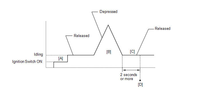
CONFIRMATION DRIVING PATTERN
HINT:
- After repair has been completed, clear the DTC and then check that the vehicle has returned to normal by performing the following All Readiness check procedure.
Click here
- When clearing the permanent DTCs, refer to the "CLEAR PERMANENT DTC" procedure.
Click here
- Connect the GTS to the DLC3.
- Turn the ignition switch to ON.
- Turn the GTS on.
- Clear the DTCs (even if no DTCs are stored, perform the clear DTC procedure).
- Turn the ignition switch off and wait for at least 30 seconds.
- Turn the ignition switch to ON [A].
- Turn the GTS on.
- Start the engine.
- With the vehicle stationary, fully depress and release the accelerator pedal [B].
- Idle the engine for 2 seconds or more [C].
- Enter the following menus: Powertrain / Engine / Trouble Codes [D].
- Read the pending DTCs.
HINT:
- If a pending DTC is output, the system is malfunctioning.
- If a pending DTC is not output, perform the following procedure.
- Enter the following menus: Powertrain / Engine / Utility / All Readiness.
- Input the DTC: P21352B.
- Check the DTC judgment result.
GTS Display
Description
NORMAL
- DTC judgment completed
- System normal
ABNORMAL
- DTC judgment completed
- System abnormal
INCOMPLETE
- DTC judgment not completed
- Perform driving pattern after confirming DTC enabling conditions
HINT:
- If the judgment result is NORMAL, the system is normal.
- If the judgment result is ABNORMAL, the system is malfunctioning.
- If the judgment result is INCOMPLETE, perform steps [B] through [D] again.
- [A] to [D]: Normal judgment procedure.
The normal judgment procedure is used to complete DTC judgment and also used when clearing permanent DTCs.
- When clearing the permanent DTCs, do not disconnect the cable from the auxiliary battery terminal or attempt to clear the DTCs during this procedure, as doing so will clear the universal trip and normal judgment histories.
FAIL-SAFE
When this DTC is stored, the ECM enters fail-safe mode. During fail-safe mode, the ECM cuts the current to the throttle actuator, and the throttle valve is returned to a 7.5° throttle valve opening angle by the return spring. The ECM then adjusts the engine output by controlling the fuel injection (intermittent fuel-cut) and ignition timing, in accordance with the accelerator pedal angle, to allow the vehicle to continue running at a minimal speed. If the accelerator pedal is depressed firmly and gently, the vehicle can be driven slowly.
Fail-safe mode continues until a pass condition is detected, and the ignition switch is turned off.
WIRING DIAGRAM
Refer to DTC P012011.
Click here
CAUTION / NOTICE / HINT
HINT:
Read Freeze Frame Data using the GTS. The ECM records vehicle and driving condition information as Freeze Frame Data the moment a DTC is stored. When troubleshooting, Freeze Frame Data can help determine if the vehicle was moving or stationary, if the engine was warmed up or not, if the air fuel ratio was lean or rich, and other data from the time the malfunction occurred.
PROCEDURE
| 1. |
READ VALUE USING GTS (THROTTLE POSITION SENSOR VOLTAGE) |
(a) Enter the following menus.
Powertrain > Engine > Data List|
Tester Display |
|---|
| Throttle Position Sensor No.1 Voltage |
|
Throttle Position Sensor No.2 Voltage |
(b) Read the values displayed on the GTS.
|
Result | Proceed to |
|---|---|
|
Value of both Throttle Position Sensor No.1 Voltage and Throttle Position Sensor No.2 Voltage are less than 0.56 V |
A |
| Value of both Throttle Position Sensor No.1 Voltage and Throttle Position Sensor No.2 Voltage are higher than 4.535 V |
B |
| Value of both Throttle Position Sensor No.1 Voltage and Throttle Position Sensor No.2 Voltage are between 0.56 V and 4.535 V |
C |
| B |
.gif) | GO TO STEP 4 |
| C |
| GO TO STEP 6 |
|
.gif)
| 2. |
CHECK HARNESS AND CONNECTOR (THROTTLE POSITION SENSOR - ECM) |
(a) Disconnect the throttle body with motor assembly connector.
(b) Disconnect the ECM connector.
(c) Measure the resistance according to the value(s) in the table below.
Standard Resistance:
|
Tester Connection | Condition |
Specified Condition |
|---|---|---|
|
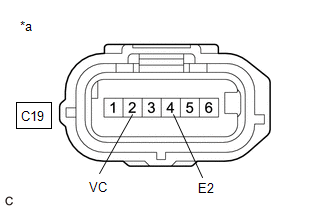
C19-2 (VC) - C76-109 (VCTA) |
Always | Below 1 Ω |
|
C19-1 (VTA) - C76-108 (VTA1) |
Always | Below 1 Ω |
|
C19-3 (VTA2) - C76-87 (VTA2) |
Always | Below 1 Ω |
|
C19-4 (E2) - C76-110 (ETA) |
Always | Below 1 Ω |
|
C19-2 (VC) or C76-109 (VCTA) - Body ground and other terminals |
Always | 10 kΩ or higher |
|
C19-1 (VTA) or C76-108 (VTA1) - Body ground and other terminals |
Always | 10 kΩ or higher |
|
C19-3 (VTA2) or C76-87 (VTA2) - Body ground and other terminals |
Always | 10 kΩ or higher |
| NG | | REPAIR OR REPLACE HARNESS OR CONNECTOR |
|
| 3. |
INSPECT TERMINAL VOLTAGE (POWER SOURCE OF THROTTLE POSITION SENSOR) |
|
*a | Front view of wire harness connector (to Throttle Body with Motor Assembly) |
(a) Disconnect the throttle body with motor assembly connector.
(b) Turn the ignition switch to ON.
(c) Measure the voltage according to the value(s) in the table below.
Standard Voltage:
|
Tester Connection | Condition |
Specified Condition |
|---|---|---|
|
C19-2 (VC) - C19-4 (E2) |
Ignition switch ON | 4.5 to 5.5 V |
HINT:
Perform "Inspection After Repair" after replacing the throttle body with motor assembly.
Click here
| OK | | REPLACE THROTTLE BODY WITH MOTOR ASSEMBLY |
| NG | | REPLACE ECM
|
| 4. |
CHECK HARNESS AND CONNECTOR (GROUND CIRCUIT) |
HINT:
Make sure that the connector is properly connected. If it is not, securely connect it and check for DTCs again.
(a) Disconnect the throttle body with motor assembly connector.
(b) Measure the resistance according to the value(s) in the table below.
Standard Resistance:
|
Tester Connection | Condition |
Specified Condition |
|---|---|---|
|
C19-4 (E2) - Body ground |
Always | Below 1 Ω |
HINT:
Perform "Inspection After Repair" after replacing the throttle body with motor assembly.
Click here
| OK | | REPLACE THROTTLE BODY WITH MOTOR ASSEMBLY |
|
| 5. |
CHECK HARNESS AND CONNECTOR (THROTTLE POSITION SENSOR - ECM) |
(a) Disconnect the throttle body with motor assembly connector.
(b) Disconnect the ECM connector.
(c) Measure the resistance according to the value(s) in the table below.
Standard Resistance:
|
Tester Connection | Condition |
Specified Condition |
|---|---|---|
|
C19-2 (VC) - C76-109 (VCTA) |
Always | Below 1 Ω |
|
C19-1 (VTA) - C76-108 (VTA1) |
Always | Below 1 Ω |
|
C19-3 (VTA2) - C76-87 (VTA2) |
Always | Below 1 Ω |
|
C19-4 (E2) - C76-110 (ETA) |
Always | Below 1 Ω |
|
C19-2 (VC) or C76-109 (VCTA) - Other terminals |
Always | 10 kΩ or higher |
|
C19-1 (VTA) or C76-108 (VTA1) - Other terminals |
Always | 10 kΩ or higher |
|
C19-3 (VTA2) or C76-87 (VTA2) - Other terminals |
Always | 10 kΩ or higher |
| OK | | REPLACE ECM
|
| NG | | REPAIR OR REPLACE HARNESS OR CONNECTOR |
| 6. |
CHECK HARNESS AND CONNECTOR (SHORT CIRCUIT) |
(a) Disconnect the throttle body with motor assembly connector.
(b) Measure the resistance according to the value(s) in the table below.
Standard Resistance:
|
Tester Connection | Condition |
Specified Condition |
|---|---|---|
|
C19-1 (VTA) - C19-3 (VTA2) |
Always | 10 kΩ or higher |
HINT:
Perform "Inspection After Repair" after replacing the throttle body with motor assembly.
Click here
| OK | | REPLACE THROTTLE BODY WITH MOTOR ASSEMBLY |
|
| 7. |
CHECK HARNESS AND CONNECTOR (SHORT CIRCUIT) |
(a) Disconnect the throttle body with motor assembly connector.
(b) Disconnect the ECM connector.
(c) Measure the resistance according to the value(s) in the table below.
Standard Resistance:
|
Tester Connection | Condition |
Specified Condition |
|---|---|---|
|
C19-1 (VTA) - C19-3 (VTA2) |
Always | 10 kΩ or higher |
HINT:
If the resistance changes when the ECM connector is disconnected, there is an internal short in the ECM.
| OK | | REPLACE ECM
|
| NG | | REPAIR OR REPLACE HARNESS OR CONNECTOR (THROTTLE POSITION SENSOR - ECM) |
READ NEXT:
 Throttle/Pedal Position Sensor/Switch "D"/"E" Voltage Correlation Signal Cross Coupled (P21382B)
DESCRIPTION HINT: These DTCs relate to the accelerator pedal position sensor.
Refer to DTC P212012. Click here
DTC No. Detection Item
DTC Detection Condition Trouble Area
MIL
A/F (O2) Sensor Signal Biased/Stuck Lean Bank 1 Sensor 1 Circuit Current Above Threshold (P219519,P219524,P219618,P219623)
DESCRIPTION Refer to DTC P003012. Click here
HINT: Although the DTC titles say O2 sensor, these DTCs relate to the air fuel ratio sensor (sensor 1).
DTC No. Detection Item
DTC Detecti
Cylinder 1 Injector "B" Circuit Open (P21CF13,P21D013-P21D213)
DESCRIPTION The D-4S system has two injection systems. One is an in-cylinder direct injection system that directly injects pressurized fuel into the combustion chamber. The other is an intake port inj
SEE MORE:
 TRAC does not Operate
DESCRIPTION
When TRAC or VSC is operating, the skid control ECU (brake actuator
assembly) blinks the slip indicator light to inform the driver that slippage occurred.
When in VSC off mode, or TRAC and VSC are disabled, the multi-information
display in the combination meter assembly displays &q
Front Radar Sensor Optical Axis Misalignment Malfunction (C1A1100)
DESCRIPTION
The millimeter wave radar sensor assembly performs self-diagnosis
to check for misalignment of its beam axis. If misalignment is detected, the millimeter
wave radar sensor assembly stores DTC C1A1100.
DTC No.
Detection Item
DTC Detection Condition
