Toyota Corolla Cross: Terminals Of Ecu
TERMINALS OF ECU
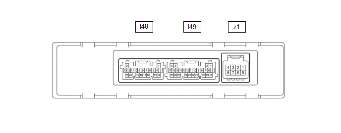
CHECK AIR CONDITIONING AMPLIFIER ASSEMBLY
HINT:
- Check from the rear of the connector while it is connected to the air conditioning amplifier assembly.
- Make sure to wait at least 2 minutes after turning the ignition switch off before performing an ECU terminal inspection.
|
Terminal No. (Symbol) |
Terminal Description | Condition |
Specified Condition |
|---|---|---|---|
|
I48-1 (TAM) - Body ground |
Thermistor assembly signal |
| 1.05 to 1.45 V |
| 0.64 to 0.87 V | ||
|
I48-3 (SG-1) - Body ground |
Ground for cooler thermistor (room temperature sensor) |
Always | Below 1 V |
|
I48-5 (TR) - I49-17 (GND) |
Cooler thermistor (room temperature sensor) signal |
| 1.05 to 1.45 V |
| 0.64 to 0.87 V | ||
|
I48-6 (PRE) - I49-17 (GND) |
Air conditioner pressure sensor signal |
| 4.61 V or higher*1 |
| Below 0.74 V*1 | ||
| 0.74 to 4.61 V*1 | ||
|
I48-11 (S5-3) - I49-17 (GND) |
Power supply for air conditioner pressure sensor |
Ignition switch ON | 4.75 to 5.25 V |
|
Ignition switch off | Below 1 V | ||
|
I48-14 (SG-2) - Body ground |
Ground for thermistor assembly |
Always | Below 1 V |
|
I48-15 (SG-4) - Body ground |
Ground for air conditioner pressure sensor |
Always | Below 1 V |
|
I49-1 (CANL) - I49-2 (CANH) |
CAN communication system |
CAN communication is performed |
Pulse generation |
|
I49-5 (B) - I49-17 (GND) |
Power source (Back-up) |
Always | 11 to 14 V |
|
I49-6 (IG+) - I49-17 (GND) |
Power source (IG) | Ignition switch ON |
11 to 14 V |
| Ignition switch off |
Below 1 V | ||
|
I49-7 (LIN1) - I49-17 (GND) |
LIN communication signal |
Ignition switch ON | Pulse generation (See waveform 1) |
|
I49-17 (GND) - Body ground |
Ground for main power supply |
Always | Below 1 V |
|
I49-18 (SOL+) - I49-17 (GND) |
Compressor solenoid operation signal |
| Pulse generation (See waveform 2) |
|
I49-21 (BLW) - I49-17 (GND) |
Blower motor speed control signal |
| Pulse generation (See waveform 3) |
|
z1-2 (BUS G) - Body ground | Ground for BUS IC |
Always | Below 1 V |
|
z1-3 (BUS) - z1-2 (BUS G) | BUS IC control signal |
Ignition switch ON | Pulse generation (See waveform 4) |
|
z1-4 (B BUS) - z1-2 (BUS G) | Power supply for BUS IC |
Always | 11 to 14 V |
|
z1-5 (SGA) - Body ground | Ground for No. 1 cooler thermistor |
Always | Below 1 V |
|
z1-6 (TEA) - z1-5 (SGA) |
No. 1 cooler thermistor signal |
| 1.7 to 2.1 V |
| 0.9 to 1.3 V |
- *1: While sensor voltage is 5 V.
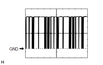
(a) Waveform 1:
|
Item | Content |
|---|---|
|
Terminal No. | I49-7 (LIN1) - I49-17 (GND) |
|
Tool Setting | 2 V/DIV., 20 ms./DIV. |
|
Condition | Ignition switch ON |
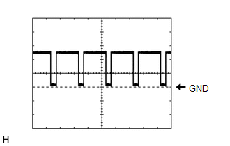
(b) Waveform 2:

|
Item | Content |
|---|---|
|
Terminal No. | I49-18 (SOL+) - I49-17 (GND) |
|
Tool Setting | 5 V/DIV., 500 μs./DIV. |
|
Condition |
|
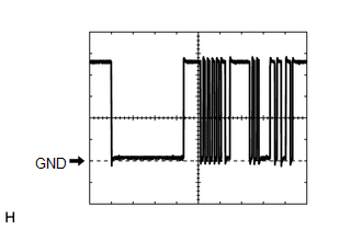
(c) Waveform 3:
|
Item | Content |
|---|---|
|
Terminal No. | I49-21 (BLW) - I49-17 (GND) |
|
Tool Setting | 2 V/DIV., 1 ms./DIV. |
|
Condition |
|
(d) Waveform 4:
|
Item | Content |
|---|---|
|
Terminal No. | z1-3 (BUS) - z1-2 (BUS G) |
|
Tool Setting | 2 V/DIV., 2 ms./DIV. |
|
Condition | Ignition switch ON |
CHECK AIR CONDITIONING CONTROL ASSEMBLY

HINT:
Check from the rear of the connector while it is connected to the air conditioning control assembly.
|
Terminal No. (Symbol) |
Terminal Description | Condition |
Specified Condition |
|---|---|---|---|
|
I37-7 (LIN1) - Body ground |
LIN communication signal |
Ignition switch ON | Pulse generation (See waveform) |
|
I37-8 (ILL+) - Body ground |
Illumination signal | Taillight off |
Below 1 V |
| Taillight on |
11 to 14 V | ||
|
I37-9 (IG+) - I37-13 (GND) |
Power source (IG) | Ignition switch off |
Below 1 V |
| Ignition switch ON |
11 to 14 V | ||
|
I37-13 (GND) - Body ground |
Ground for air conditioning control assembly |
Always | Below 1 V |
|
I37-14 (ILL-) - Body ground |
Illumination signal | Always |
Below 1 V |
(a) Waveform:
|
Item | Content |
|---|---|
|
Terminal No. | I37-7 (LIN1) - Body ground |
|
Tool Setting | 2 V/DIV., 20 ms./DIV. |
|
Condition | Ignition switch ON |

