Toyota Corolla Cross: Terminals Of Ecu
TERMINALS OF ECU
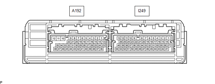
HYBRID VEHICLE CONTROL ECU
|
Connector Code | Terminal No. |
Symbol | Terminal Description |
|---|---|---|---|
|
I249 | 1 |
E1 | ECU ground |
|
2 | - |
- | |
| 3 |
SMRB | System main relay operation signal output (SMRB) | |
|
4 | M |
Transmission control input | |
|
5 | IGB |
IGB signal input | |
|
6 | INDD |
Shift position indicator signal input | |
|
7 | INDP |
Shift position indicator signal input | |
|
8 | +B1 |
Power source (+B) | |
|
9 | CA4H |
CAN communication signal | |
|
10 | MREL |
Main relay | |
|
11 | ST2 |
Starter signal input | |
|
12 | ABFS |
Airbag activation signal input | |
|
13 | BATT |
Constant power source | |
|
14 | - |
- | |
| 15 |
- | - | |
|
16 | - |
- | |
| 17 |
INDR | Shift position indicator signal input | |
|
18 | SFTD |
Transmission control input | |
|
19 | - |
- | |
| 20 |
INDB | Shift position indicator signal input | |
|
21 | INDN |
Shift position indicator signal input | |
|
22 | CA4L |
CAN communication signal | |
|
23 | PLKC |
Shift lock release request signal output | |
|
24 | BL |
Back-up light relay operation signal output | |
|
25 | - |
- | |
| 26 |
IGP | IGP signal input | |
|
27 | SMRG |
System main relay operation signal output (SMRG) | |
|
28 | - |
- | |
| 29 |
CCS | Cruise control main switch input | |
|
30 | - |
- | |
| 31 |
SFTU | Transmission control input | |
|
32 | ILK |
Interlock switch input | |
|
33 | EVSW |
EV drive mode switch signal input | |
|
34 | - |
- | |
| 35 |
- | - | |
|
36 | - |
- | |
| 37 |
PDRV*1 DMS-*2 |
Drive mode switch signal input | |
|
38 | DMS+*2 |
Drive mode switch signal input | |
|
39 | IMO |
ID code box (immobiliser code ECU) communication output | |
|
40 | - |
- | |
| 41 |
- | - | |
|
42 | - |
- | |
| 43 |
CCSG | Cruise control main switch ground | |
|
44 | - |
- | |
| 45 |
- | - | |
|
46 | - |
- | |
| 47 |
RMTG | Rear Motor temperature sensor ground | |
|
48 | RMT |
Rear Motor temperature sensor input | |
|
49 | CA3N |
CAN communication signal | |
|
50 | CA3P |
CAN communication signal | |
|
51 | CA1H |
CAN communication signal | |
|
52 | CA1L |
CAN communication signal | |
|
53 | IMI |
ID code box (immobiliser code ECU) communication input | |
|
54 | - |
- | |
|
A192 | 1 |
HMCL | MG ECU communication request signal |
|
2 | HMCH |
MG ECU communication request signal | |
|
3 | - |
- | |
| 4 |
- | - | |
|
5 | PSFT |
Shift lever position sensor power source | |
|
6 | - |
- | |
| 7 |
ST1- | Brake cancel switch input | |
|
8 | IGR |
IGR signal input | |
|
9 | HSDN |
MG ECU shutdown signal output | |
|
10 | - |
- | |
| 11 |
- | - | |
|
12 | E01 |
ECU ground | |
|
13 | DRN5 | ||
|
14 | - |
- | |
| 15 |
- | - | |
|
16 | LIN3 |
LIN communication signal | |
|
17 | - |
- | |
| 18 |
DB2 | Shift lever position signal input | |
|
19 | PR |
Shift lever position signal input | |
|
20 | DB1 |
Shift lever position signal input | |
|
21 | R |
Shift lever position signal input | |
|
22 | STP |
Stop light switch signal input | |
|
23 | - |
- | |
| 24 |
E12 | ECU ground | |
|
25 | EPA2 |
Accelerator pedal sensor assembly ground | |
|
26 | VCP2 |
Accelerator pedal sensor assembly power source | |
|
27 | - |
- | |
| 28 |
N | Shift lever position signal input | |
|
29 | PNB |
Shift lever position signal input | |
|
30 | - |
- | |
| 31 |
P | Shift lever position signal input | |
|
32 | IWP |
Inverter water pump assembly signal output | |
|
33 | NIWP |
Inverter water pump assembly signal input | |
|
34 | - |
- | |
| 35 |
DDFS | DC/DC converter fail-safe signal | |
|
36 | VPA |
Accelerator pedal position detection | |
|
37 | EPA |
Accelerator pedal sensor assembly ground | |
|
38 | VCPA |
Accelerator pedal sensor assembly power source | |
|
39 | VPA2 |
Accelerator pedal position detection | |
|
40 | - |
- | |
| 41 |
- | - | |
|
42 | - |
- | |
| 43 |
- | - | |
|
44 | - |
- | |
| 45 |
- | - | |
|
46 | - |
- | |
| 47 |
- | - | |
|
48 | - |
- |
- *1: for Push Type Switch
- *2: for Toggle Type Switch


