Toyota Corolla Cross: Taillight Relay Circuit
DESCRIPTION
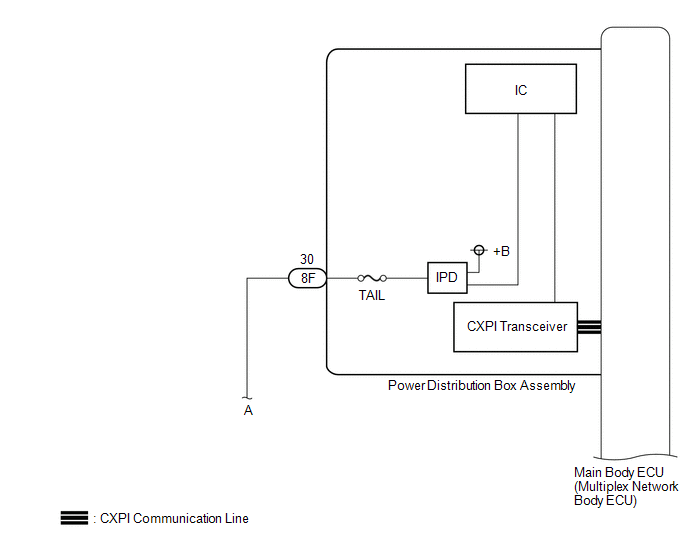
The main body ECU (multiplex network body ECU) controls the operation of the TAIL relay.
WIRING DIAGRAM
CAUTION / NOTICE / HINT
NOTICE:
- Before replacing the main body ECU (multiplex network body ECU), refer to Registration.
- First perform the communication function inspections in How to Proceed with Troubleshooting to confirm that there are no CXPI communication malfunctions before troubleshooting this symptom.
Click here
.gif)
PROCEDURE
|
1. | READ VALUE USING GTS |
(a) Using the GTS, read the Data List.
Body Electrical > Power Distribution Box > Data List|
Tester Display | Measurement Item |
Range | Normal Condition |
Diagnostic Note |
|---|---|---|---|---|
|
Tail Light Input Signal |
Tail light input | OFF or ON |
OFF: Taillight is not input ON: Tail light is input |
- |
|
Tester Display |
|---|
| Tail Light Input Signal |
OK:
Display changes according to the taillight illumination condition.
| NG | .gif) | REPLACE MAIN BODY ECU (MULTIPLEX NETWORK BODY ECU)
|
|
.gif)
| 2. |
READ VALUE USING GTS |
(a) Turn the light control switch to the TAIL position.
(b) Using the GTS, read the Data List.
Body Electrical > Power Distribution Box > Data List|
Tester Display | Measurement Item |
Range | Normal Condition |
Diagnostic Note |
|---|---|---|---|---|
|
Tail Light Fuse Shut Off Status |
Tail light fuse condition |
OFF or ON | OFF: Taillight fuse not shut off ON: Taillight fuse shut off |
- |
|
Tester Display |
|---|
| Tail Light Fuse Shut Off Status |
OK:
The Data List value displays "OFF".
| NG | | GO TO STEP 4 |
|
| 3. |
READ VALUE USING GTS |
(a) Using the GTS, read the Data List.
Body Electrical > Power Distribution Box > Data List|
Tester Display | Measurement Item |
Range | Normal Condition |
Diagnostic Note |
|---|---|---|---|---|
|
Tail Light Output Signal |
Tail light output | OFF or ON |
OFF: Taillight is not output ON: Tail light is output |
- |
|
Tester Display |
|---|
| Tail Light Output Signal |
OK:
Display changes according to the taillight illumination condition.
| OK | | PROCEED TO NEXT SUSPECTED AREA SHOWN IN PROBLEM SYMPTOMS TABLE
|
| NG | | REPLACE MAIN BODY ECU (MULTIPLEX NETWORK BODY ECU)
|
| 4. |
INSPECT REAR COMBINATION LIGHT ASSEMBLY LH |
(a) Disconnect the S14 rear combination light assembly LH connector.
(b) Turn the light control switch to the AUTO (OFF) position.
NOTICE:
If the low beam headlights or clearance lights illuminate when the ignition switch is turned ON, shine a light on the automatic light control sensor to turn the low beam headlights off before operating the headlight dimmer switch.
(c) Turn the light control switch to the TAIL position.
(d) Using the GTS, read the Data List.
Body Electrical > Power Distribution Box > Data List|
Tester Display | Measurement Item |
Range | Normal Condition |
Diagnostic Note |
|---|---|---|---|---|
|
Tail Light Fuse Shut Off Status |
Tail light fuse condition |
OFF or ON | OFF: Taillight fuse not shut off ON: Taillight fuse shut off |
- |
|
Tester Display |
|---|
| Tail Light Fuse Shut Off Status |
OK:
The Data List value displays "OFF".
| OK | | REPLACE REAR COMBINATION LIGHT ASSEMBLY LH |
|
| 5. |
INSPECT REAR COMBINATION LIGHT ASSEMBLY RH |
(a) Disconnect the S15 rear combination light assembly RH connector.
(b) Turn the light control switch to the AUTO (OFF) position.
NOTICE:
If the low beam headlights or clearance lights illuminate when the ignition switch is turned ON, shine a light on the automatic light control sensor to turn the low beam headlights off before operating the headlight dimmer switch.
(c) Turn the light control switch to the TAIL position.
(d) Using the GTS, read the Data List.
Body Electrical > Power Distribution Box > Data List|
Tester Display | Measurement Item |
Range | Normal Condition |
Diagnostic Note |
|---|---|---|---|---|
|
Tail Light Fuse Shut Off Status |
Tail light fuse condition |
OFF or ON | OFF: Taillight fuse not shut off ON: Taillight fuse shut off |
- |
|
Tester Display |
|---|
| Tail Light Fuse Shut Off Status |
OK:
The Data List value displays "OFF".
| OK | | REPLACE REAR COMBINATION LIGHT ASSEMBLY RH |
|
| 6. |
INSPECT REAR LIGHT ASSEMBLY LH |
(a) Disconnect the U44 rear light assembly LH connector.
(b) Turn the light control switch to the AUTO (OFF) position.
NOTICE:
If the low beam headlights or clearance lights illuminate when the ignition switch is turned ON, shine a light on the automatic light control sensor to turn the low beam headlights off before operating the headlight dimmer switch.
(c) Turn the light control switch to the TAIL position.
(d) Using the GTS, read the Data List.
Body Electrical > Power Distribution Box > Data List|
Tester Display | Measurement Item |
Range | Normal Condition |
Diagnostic Note |
|---|---|---|---|---|
|
Tail Light Fuse Shut Off Status |
Tail light fuse condition |
OFF or ON | OFF: Taillight fuse not shut off ON: Taillight fuse shut off |
- |
|
Tester Display |
|---|
| Tail Light Fuse Shut Off Status |
OK:
The Data List value displays "OFF".
| OK | | REPLACE REAR LIGHT ASSEMBLY LH |
|
| 7. |
INSPECT REAR LIGHT ASSEMBLY RH |
(a) Disconnect the U43 rear light assembly RH connector.
(b) Turn the light control switch to the AUTO (OFF) position.
NOTICE:
If the low beam headlights or clearance lights illuminate when the ignition switch is turned ON, shine a light on the automatic light control sensor to turn the low beam headlights off before operating the headlight dimmer switch.
(c) Turn the light control switch to the TAIL position.
(d) Using the GTS, read the Data List.
Body Electrical > Power Distribution Box > Data List|
Tester Display | Measurement Item |
Range | Normal Condition |
Diagnostic Note |
|---|---|---|---|---|
|
Tail Light Fuse Shut Off Status |
Tail light fuse condition |
OFF or ON | OFF: Taillight fuse not shut off ON: Taillight fuse shut off |
- |
|
Tester Display |
|---|
| Tail Light Fuse Shut Off Status |
OK:
The Data List value displays "OFF".
| OK | | REPLACE REAR LIGHT ASSEMBLY RH |
|
| 8. |
INSPECT LICENSE PLATE LIGHT ASSEMBLY LH |
(a) Disconnect the U2 license plate light assembly LH connector.
(b) Turn the light control switch to the AUTO (OFF) position.
NOTICE:
If the low beam headlights or clearance lights illuminate when the ignition switch is turned ON, shine a light on the automatic light control sensor to turn the low beam headlights off before operating the headlight dimmer switch.
(c) Turn the light control switch to the TAIL position.
(d) Using the GTS, read the Data List.
Body Electrical > Power Distribution Box > Data List|
Tester Display | Measurement Item |
Range | Normal Condition |
Diagnostic Note |
|---|---|---|---|---|
|
Tail Light Fuse Shut Off Status |
Tail light fuse condition |
OFF or ON | OFF: Taillight fuse not shut off ON: Taillight fuse shut off |
- |
|
Tester Display |
|---|
| Tail Light Fuse Shut Off Status |
OK:
The Data List value displays "OFF".
| OK | | REPLACE LICENSE PLATE LIGHT ASSEMBLY LH |
|
| 9. |
INSPECT LICENSE PLATE LIGHT ASSEMBLY RH |
(a) Disconnect the U3 license plate light assembly RH connector.
(b) Turn the light control switch to the AUTO (OFF) position.
NOTICE:
If the low beam headlights or clearance lights illuminate when the ignition switch is turned ON, shine a light on the automatic light control sensor to turn the low beam headlights off before operating the headlight dimmer switch.
(c) Turn the light control switch to the TAIL position.
(d) Using the GTS, read the Data List.
Body Electrical > Power Distribution Box > Data List|
Tester Display | Measurement Item |
Range | Normal Condition |
Diagnostic Note |
|---|---|---|---|---|
|
Tail Light Fuse Shut Off Status |
Tail light fuse condition |
OFF or ON | OFF: Taillight fuse not shut off ON: Taillight fuse shut off |
- |
|
Tester Display |
|---|
| Tail Light Fuse Shut Off Status |
OK:
The Data List value displays "OFF".
| OK | | REPLACE LICENSE PLATE LIGHT ASSEMBLY RH |
|
| 10. |
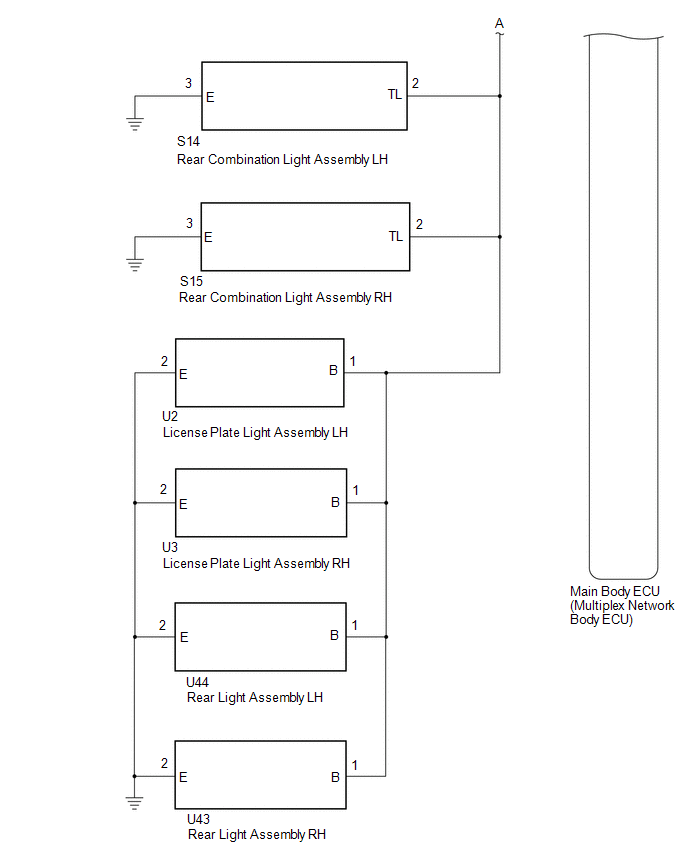
CHECK HARNESS AND CONNECTOR(POWER DISTRIBUTION BOX ASSEMBLY - REAR COMBINATION LIGHT ASSEMBLY AND LICENSE PLATE LIGHT ASSEMBLY |
(a) Disconnect the S14 rear combination light assembly LH connector.
(b) Disconnect the S15 rear combination light assembly RH connector.
(c) Disconnect the U2 license plate light assembly LH connector.
(d) Disconnect the U3 license plate light assembly RH connector.
(e) Disconnect the U44 rear light assembly LH connector.
(f) Disconnect the U43 rear light assembly RH connector.
(g) Disconnect the cable from the negative (-) auxiliary battery terminal.
(h) Disconnect the 8F power distribution box assembly connector.
(i) Measure the resistance according to the value(s) in the table below.
Standard Resistance:
|
Tester Connection | Condition |
Specified Condition |
|---|---|---|
|
S14-2 (TL) - Body ground |
Always | 10 kΩ or higher |
|
S15-2 (TL) - Body ground |
Always | 10 kΩ or higher |
|
U2-1 (B) - Body ground |
Always | 10 kΩ or higher |
|
U3-1 (B) - Body ground |
Always | 10 kΩ or higher |
|
U44-1 (B) - Body ground |
Always | 10 kΩ or higher |
|
U43-1 (B) - Body ground |
Always | 10 kΩ or higher |
|
8F-30 - Body ground | Always |
10 kΩ or higher |
| OK | | REPLACE MAIN BODY ECU (MULTIPLEX NETWORK BODY ECU)
|
| NG | | REPAIR OR REPLACE HARNESS OR CONNECTOR |


