Toyota Corolla Cross: System Voltage Circuit Short to Ground or Open (P056014)
MONITOR DESCRIPTION
The auxiliary battery supplies electricity to the ECM even when the ignition switch is off. This power allows the ECM to store data such as DTC history, Freeze Frame Data and fuel trim values. If the auxiliary battery voltage falls below a minimum level, the memory is cleared and the ECM determines that there is a malfunction in the power supply circuit. The next time the engine is started, the ECM will illuminate the MIL and store this DTC.
|
DTC No. | Detection Item |
DTC Detection Condition | Trouble Area |
MIL | Note |
|---|---|---|---|---|---|
|
P056014 | System Voltage Circuit Short to Ground or Open |
An open or short in the ECM backup power source circuit (1 trip detection logic). |
| Comes on |
|
MONITOR STRATEGY
|
Related DTCs | P0562: ECM system voltage range check (low voltage) |
|
Required Sensors/Components (Main) | ECM |
|
Required Sensors/Components (Related) |
- |
| Frequency of Operation |
Continuous |
| Duration |
3 seconds |
| MIL Operation |
Immediate |
| Sequence of Operation |
None |
TYPICAL ENABLING CONDITIONS
|
Monitor runs whenever the following DTCs are not stored |
None |
| All of the following conditions are met |
- |
| Auxiliary battery voltage |
8 V or higher |
| Ignition switch |
ON |
| Starter | Off |
TYPICAL MALFUNCTION THRESHOLDS
|
Continuous auxiliary battery voltage | Less than 3.5 V |
CONFIRMATION DRIVING PATTERN
HINT:
- After repair has been completed, clear the DTC and then check that the vehicle has returned to normal by performing the following All Readiness check procedure.
Click here
.gif)
- When clearing the permanent DTCs, refer to the "CLEAR PERMANENT DTC" procedure.
Click here
- Connect the GTS to the DLC3.
- Turn the ignition switch to ON.
- Turn the GTS on.
- Clear the DTCs (even if no DTCs are stored, perform the clear DTC procedure).
- Turn the ignition switch off and wait for at least 30 seconds.
- Turn the ignition switch to ON.
- Turn the GTS on.
- Wait 5 seconds or more [A].
- Enter the following menus: Powertrain / Engine / Trouble Codes [B].
- Read the pending DTCs.
HINT:
- If a pending DTC is output, the system is malfunctioning.
- If a pending DTC is not output, perform the following procedure.
- Enter the following menus: Powertrain / Engine / Utility / All Readiness.
- Input the DTC: P056014.
- Check the DTC judgment result.
GTS Display
Description
NORMAL
- DTC judgment completed
- System normal
ABNORMAL
- DTC judgment completed
- System abnormal
INCOMPLETE
- DTC judgment not completed
- Perform driving pattern after confirming DTC enabling conditions
HINT:
- If the judgment result is NORMAL, the system is normal.
- If the judgment result is ABNORMAL, the system is malfunctioning.
- [A] to [B]: Normal judgment procedure.
The normal judgment procedure is used to complete DTC judgment and also used when clearing permanent DTCs.
- When clearing the permanent DTCs, do not disconnect the cable from the auxiliary battery terminal or attempt to clear the DTCs during this procedure, as doing so will clear the universal trip and normal judgment histories.
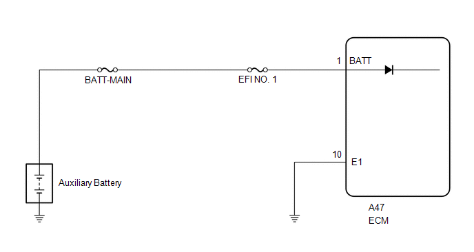
WIRING DIAGRAM
CAUTION / NOTICE / HINT
NOTICE:
- Inspect the fuses for circuits related to this system before performing the following procedure.
- After the ignition switch is turned off, there may be a waiting time before disconnecting the negative (-) auxiliary battery terminal.
Click here
- When disconnecting and reconnecting the auxiliary battery.
HINT:
When disconnecting and reconnecting the auxiliary battery, there is an automatic learning function that completes learning when the respective system is used.
Click here
HINT:
Read Freeze Frame Data using the GTS. The ECM records vehicle and driving condition information as Freeze Frame Data the moment a DTC is stored. When troubleshooting, Freeze Frame Data can help determine if the vehicle was moving or stationary, if the engine was warmed up or not, if the air fuel ratio was lean or rich, and other data from the time the malfunction occurred.
PROCEDURE
| 1. |
INSPECT AUXILIARY BATTERY |
Click here
OK:
Auxiliary battery voltage is between 11 to 14 V.
| NG | .gif) | CHARGE OR REPLACE AUXILIARY BATTERY |
|
.gif)
| 2. |
CHECK AUXILIARY BATTERY TERMINAL |
(a) Check that the auxiliary battery terminals are not loose or corroded.
OK:
Auxiliary battery terminals are not loose or corroded.
| NG | | REPAIR OR REPLACE AUXILIARY BATTERY TERMINAL |
|
| 3. |
CHECK TERMINAL VOLTAGE (POWER SOURCE OF ECM) |
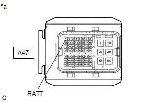
|
*a | Front view of wire harness connector (to ECM) |
(a) Disconnect the ECM connector.
(b) Measure the voltage according to the value(s) in the table below.
Standard Voltage:
|
Tester Connection | Condition |
Specified Condition |
|---|---|---|
|
A47-1 (BATT) - Body ground |
Always | 11 to 14 V |
| NG | | REPAIR OR REPLACE HARNESS OR CONNECTOR (AUXILIARY BATTERY - ECM) |
|
| 4. |
CLEAR DTC |
(a) Clear the DTCs.
Powertrain > Engine > Clear DTCs(b) Turn the ignition switch off and wait for at least 30 seconds.
|
| 5. |
CHECK WHETHER DTC OUTPUT RECURS (DTC P056014) |
(a) Drive the vehicle in accordance with the driving pattern described in Confirmation Driving Pattern.
(b) Read the DTCs.
Powertrain > Engine > Trouble Codes|
Result | Proceed to |
|---|---|
|
DTCs are not output | A |
|
DTC P056014 is output |
B |
| A |
| CHECK FOR INTERMITTENT PROBLEMS |
| B |
| REPLACE ECM |
READ NEXT:
 Internal Control Module Random Access Memory (RAM) Error Data Memory Failure (P060444)
MONITOR DESCRIPTION The ECM continuously monitors its internal memory status. This self-check ensures that the ECM is functioning properly. The ECM memory status is diagnosed by internal mirroring of
Control Module Processor (Brake Override System Output Signal) Component Failure (P060609)
DESCRIPTION The ECM calculates and compares the accelerator opening angle command value used for control and the value used for monitoring, after corrected by the brake override system.
DTC No.
Control Module Processor Watchdog/Safety MCU Failure (P060647)
MONITOR DESCRIPTION The ECM continuously monitors its main CPU and monitor IC. This self-check ensures that the ECM is functioning properly. If outputs from main CPU and monitor IC are different and d
SEE MORE:
 Operation Check
OPERATION CHECK CHECK CUSTOMIZE PARAMETERS NOTICE:
The operation check below is based on the non-customized initial condition of the vehicle.
Click here
HINT:
The switches described in this text are the switches for transmitting signals. The switches are built into the electrical key tra
Stop Lamp Relay Actuator Stuck On (C13807E)
DESCRIPTION
When any of the following conditions are met, the skid control
ECU (brake actuator assembly) sets the drive output (STPO) ON which operates the
stop light control relay (stop light switch assembly) and turns on the stop lights.
Illumination Conditions:
Pre-collision brake is
