Toyota Corolla Cross: System Malfunction Message is Displayed on the Multi-information Display
SYSTEM DESCRIPTION
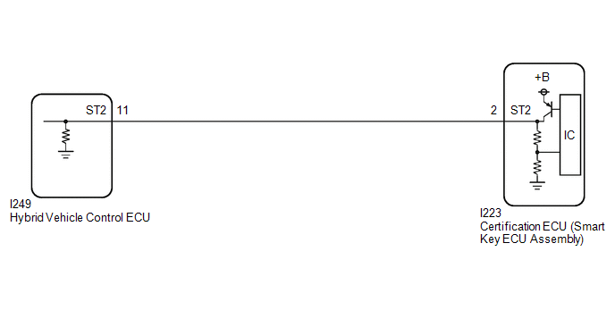
If an abnormal vehicle speed information is detected by the certification ECU (smart key ECU assembly), a system malfunction message is displayed on the multi-information display.
WIRING DIAGRAM

CAUTION / NOTICE / HINT
NOTICE:
- When using the GTS with the ignition switch off, connect the GTS to the DLC3 and turn a courtesy light switch on and off at intervals of 1.5 seconds or less until communication between the GTS and the vehicle begins.
Then select Model Code "KEY REGIST" under manual mode and enter the following menus: Body Electrical / Start Key(CAN). While using the GTS, periodically turn a courtesy light switch on and off at intervals of 1.5 seconds or less to maintain communication between the GTS and the vehicle.
- The smart key system (for Start Function) uses the LIN communication system and CAN communication system. Inspect the communication function by following How to Proceed with Troubleshooting. Troubleshoot the smart key system (for Start Function) after confirming that the communication systems are functioning properly.
Click here
.gif)
- Before replacing the certification ECU (smart key ECU assembly), refer to Registration.
Click here
.gif)
PROCEDURE
|
1. | CHECK FOR DTC |
(a) Check for DTCs.
Body Electrical > Smart Key > Trouble Codes Body Electrical > Power Source Control > Trouble Codes|
Result | Proceed to |
|---|---|
|
DTCs are not output | A |
|
DTC is output. | B |
| B |
.gif) | GO TO SMART KEY SYSTEM (for Entry Function) (DIAGNOSTIC TROUBLE CODE CHART) |
|
| 2. |
READ VALUE USING GTS (VEHICLE RUNNING CONDITION (LINE)) |
(a) Read the Data List according to the display on the GTS.
Body Electrical > Power Source Control > Data List|
Tester Display | Measurement Item |
Range | Normal Condition |
Diagnostic Note |
|---|---|---|---|---|
|
Vehicle Running Condition (Line) |
Vehicle being driven or stopped |
Stop or Driving | Stop: Vehicle stopped Driving: Vehicle being driven at 5 km/h (3 mph) or more |
- |
|
Tester Display |
|---|
| Vehicle Running Condition (Line) |
OK:
The GTS display changes correctly in response to the vehicle condition.
| OK | .gif) | REPLACE CERTIFICATION ECU (SMART KEY ECU ASSEMBLY) |
| NG | .gif) | GO TO ELECTRONICALLY CONTROLLED BRAKE SYSTEM (HOW TO PROCEED WITH TROUBLESHOOTING) |

.gif)

