Toyota Corolla Cross: System Diagram
SYSTEM DIAGRAM
HINT:
Refer to System Diagram of CAN Communication System.
- for HEV Model:
Click here .gif)
- for Gasoline Model:
Click here
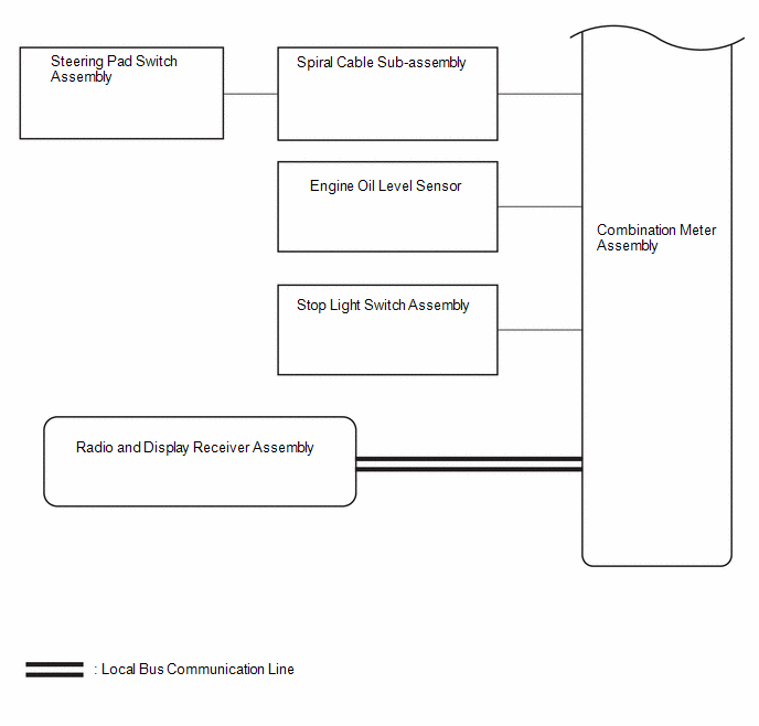
COMBINATION METER ASSEMBLY DIAGRAM

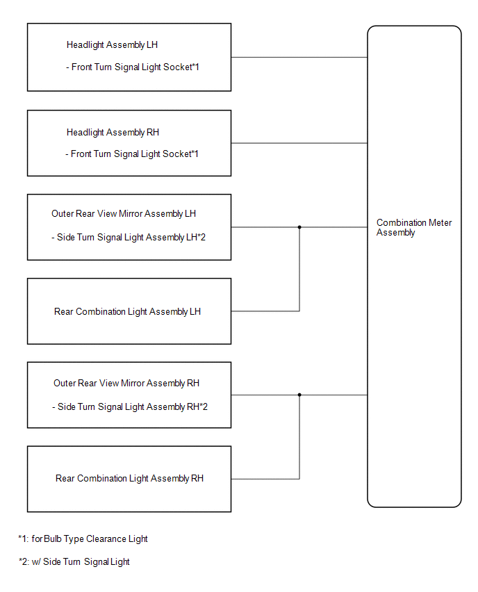
TURN SIGNAL LIGHT DIAGRAM
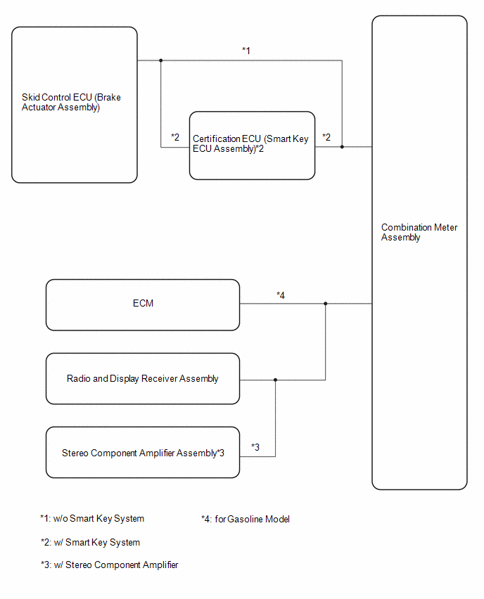
SPEED SIGNAL DIAGRAM
READ NEXT:
CAUTION / NOTICE / HINT
HINT:
Use the following procedure to troubleshoot the meter / gauge system.
*: Use the GTS.
PROCEDURE
1. VEHICLE BROUGHT TO WORKSHOP
NE
CUSTOMIZE PARAMETERS
NOTICE:
When the customer requests a change in a function, first make sure that the function can be customized.
Be sure to make a note of the current settings before cu
PROBLEM SYMPTOMS TABLE NOTICE: When replacing the combination meter assembly, always replace it with a new one. If a combination meter assembly which was installed to another vehicle is used, the info
SEE MORE:
DESCRIPTION The idle speed is controlled by the electronic throttle control system. The electronic throttle control system is comprised of: 1) one valve type throttle body with motor assembly; 2) the throttle actuator, which operates the throttle valve; 3) the throttle position sensor, which detects
DESCRIPTION
The TCM receives signals from the skid control ECU via CAN communication. When
DTCs indicating a CAN communication system malfunction are output, repair the CAN
communication system before performing troubleshooting for each corresponding ECU
or sensor.
DTC No.


