Toyota Corolla Cross: System Diagram
SYSTEM DIAGRAM
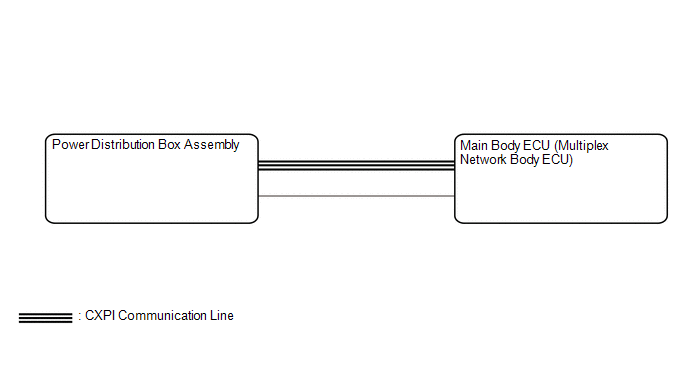
READ NEXT:
SYSTEM DESCRIPTION
LOAD OPERATION OUTPUT
(a) Load is turned on or off according to the operation signals and switch signals
from each ECU.
Components
Power Distribution Box
CAUTION / NOTICE / HINT
HINT:
Use these procedures to troubleshoot the power integration system.
*: Use the GTS.
PROCEDURE
1.
VEHICLE BROUGHT TO WORKSHOP
UTILITY
ALL READINESS
(a) Power Distribution Box Assembly
Body Electrical > Power Distribution Box > Utility
Tester Display
All Readiness
SEE MORE:
INSTALLATION
CAUTION / NOTICE / HINT
COMPONENTS (INSTALLATION)
Procedure
Part Name Code
1
COMBINATION SWITCH ASSEMBLY
84390B
-
-
-
2
REMOVE CONSOLE
DESCRIPTION
The forward recognition camera monitors its optical axis status.
If it determines that the optical axis alignment has become misaligned, it will
store DTC C1AA800.
DTC No.
Detection Item
DTC Detection Condition
Trouble Area
DTC
 System Description
 Installation