Toyota Corolla Cross: System Diagram
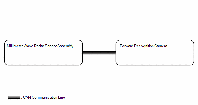
SYSTEM DIAGRAM
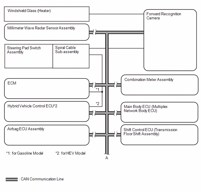
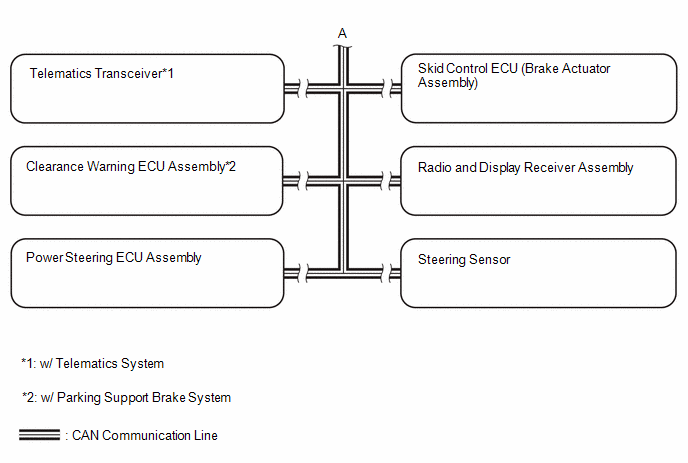
Local BUS Circuit
READ NEXT:
CAUTION / NOTICE / HINT
HINT:
Use the following procedure to troubleshoot the front camera system.
*: Use the GTS.
PROCEDURE
1.
VEHICLE BROUGHT TO WORKSHOP
OPERATION CHECK
*a
Automatic High Beam Indicator Light on Combination Meter
Assembly
AUTOMATIC HIGH BEAM OPERATION CHECK
(a) When all of the following condition
CUSTOMIZE PARAMETERS
CUSTOMIZE FRONT CAMERA SYSTEM
NOTICE:
When the customer requests a change in a function, first make sure that
the function can be customized.
Be sure to make a note o
SEE MORE:
REMOVAL CAUTION / NOTICE / HINT COMPONENTS (REMOVAL)
Procedure Part Name Code
1 REAR DOOR BELT MOULDING ASSEMBLY
75740 -
- -
2 REAR DOOR WEATHERSTRIP
67872 -
- -
3 REAR DOOR WINDOW FRAME MOULDING (CENTER PILLAR SIDE)
DTC SUMMARY MALFUNCTION DESCRIPTION These DTCs indicate that the boost converter temperature sensor (upper) value is abnormal. The cause of this malfunction may be one of the following: Internal inverter malfunction
Inverter with converter assembly internal circuit malfunction
Hybrid cool
 How To Proceed With Troubleshooting
 Removal
