Toyota Corolla Cross: Stop and Start Cancel Switch Circuit
DESCRIPTION
Stop and start control can be disabled by pressing the stop and start system cancel switch (combination switch assembly). The stop and start system cancel switch (combination switch assembly) is a momentary-type switch that switches between on and off when the switch is pressed. While stop and start control is disabled, the stop and start cancel indicator is illuminated to inform the driver.
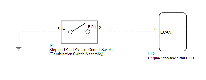
WIRING DIAGRAM
PROCEDURE
| 1. |
READ VALUE USING GTS (STOP&START CANCEL SWITCH) |
(a) In accordance with the display on the GTS, read the Data List.
Powertrain > Stop and Start > Data List|
Tester Display |
|---|
| Stop&Start Cancel Switch |
(b) Read the value when the stop and start system cancel switch (combination switch assembly) is pressed.
OK:
|
GTS Display | Condition |
Normal Condition |
|---|---|---|
|
Stop&Start Cancel Switch |
Stop and start system cancel switch (combination switch assembly) is pressed |
ON |
| Stop and start system cancel switch (combination switch assembly) is not pressed |
OFF |
| OK | .gif) | PROCEED TO NEXT SUSPECTED AREA SHOWN IN PROBLEM SYMPTOMS TABLE |
|
.gif)
| 2. |
INSPECT STOP AND START SYSTEM CANCEL SWITCH (COMBINATION SWITCH ASSEMBLY) |
Click here .gif)
| NG | | REPLACE STOP AND START SYSTEM CANCEL SWITCH (COMBINATION SWITCH ASSEMBLY) |
|
| 3. |
CHECK HARNESS AND CONNECTOR (STOP AND START SYSTEM CANCEL SWITCH (COMBINATION SWITCH ASSEMBLY) - BODY GROUND) |
(a) Disconnect the I61 stop and start system cancel switch (combination switch assembly) connector.
(b) Measure the resistance according to the value(s) in the table below.
Standard Resistance:
|
Tester Connection | Condition |
Specified Condition |
|---|---|---|
|
I61-5 (E) - Body ground |
Always | Below 1 Ω |
| NG | | REPAIR OR REPLACE HARNESS OR CONNECTOR |
|
| 4. |
CHECK HARNESS AND CONNECTOR (ENGINE STOP AND START ECU - STOP AND START SYSTEM CANCEL SWITCH (COMBINATION SWITCH ASSEMBLY)) |
(a) Disconnect the I230 engine stop and start ECU connector.
(b) Disconnect the H18 stop and start system cancel switch (combination switch assembly) connector.
(c) Measure the resistance according to the value(s) in the table below.
Standard Resistance:
|
Tester Connection | Condition |
Specified Condition |
|---|---|---|
|
I230-5 (ECAN) - I61-8 (ECU) |
Always | Below 1 Ω |
|
I230-5 (ECAN) - Body ground and other terminals |
Always | 10 kΩ or higher |
|
I61-8 (ECU) - Body ground and other terminals |
Always | 10 kΩ or higher |
| OK | | PROCEED TO NEXT SUSPECTED AREA SHOWN IN PROBLEM SYMPTOMS TABLE |
| NG | | REPAIR OR REPLACE HARNESS OR CONNECTOR |


