Toyota Corolla Cross: Steering Pad Switch Circuit
DESCRIPTION
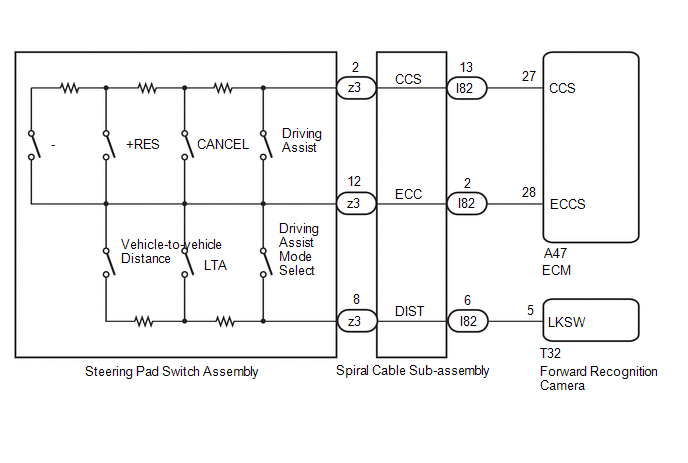
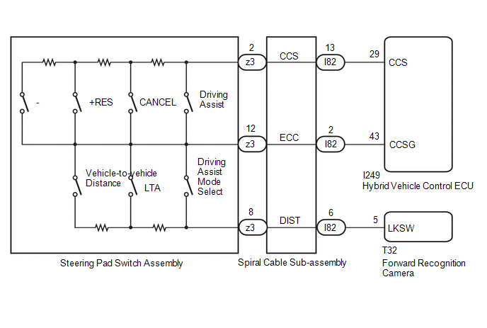
- ECM*1 or hybrid vehicle control ECU*2 performs cruise control based on signals from the driving assist switch, +RES switch, -switch, CANCEL switch (steering pad switch assembly).
- Forward recognition camera changes the driving support mode, turns LTA
ON/OFF, and sets the vehicle-to-vehicle distance based on signals from the
driving assist mode select switch, LTA switch, and vehicle-to-vehicle distance
switch (steering pad switch assembly).
- *1: for Gasoline Model
- *2: for HEV Model
WIRING DIAGRAM
for Gasoline Model
for HEV Model
CAUTION / NOTICE / HINT
NOTICE:
- The vehicle is equipped with a Supplemental Restraint System (SRS) which
includes components such as airbags. Before servicing (including removal
or installation of parts), be sure to read the precaution for Supplemental
Restraint System.
Click here
.gif)
- When replacing the forward recognition camera, always replace it with a new one. If a forward recognition camera which was installed to another vehicle is used, the information stored in the forward recognition camera will not match the information from the vehicle and a DTC may be stored.
- When the forward recognition camera has been replaced with a new one,
make sure to clear all stored vehicle control history of each system and
the forward recognition camera beam axis alignment data.
HINT:
Forward recognition camera beam axis alignment can be performed by using "One Time Recognition", "Driving Adjustment" or "Camera Axis Adjustment Value Write".
One Time Recognition: Click here
Driving Adjustment: Click here
Camera Axis Adjustment Value Write: Click here
- If the forward recognition camera has been replaced with a new one,
make sure to perform Software Version Confirmation.
Click here
- for Gasoline Model
Before replacing the ECM, refer to Registration.
Click here
- for HEV Model
Before replacing the hybrid vehicle control ECU, refer to Registration.
Click here
PROCEDURE
|
1. |
CONFIRM PROBLEM SYMPTOMS |
(a) Check the problem symptoms.
|
Result |
Proceed to |
|---|---|
|
All switches cannot be operated |
A |
|
Driving assist switch, +RES switch, -Switch, CANCEL switch cannot be operated |
B |
|
Only driving assist switch cannot be operated |
C |
|
Only +RES switch cannot be operated |
|
|
Only -switch cannot be operated |
|
|
Only CANCEL switch cannot be operated |
|
|
Only driving assist mode select switch cannot be operated |
|
|
Only vehicle-to-vehicle distance switch cannot be operated |
|
|
Only LTA switch cannot be operated |
|
|
Driving assist mode select switch, vehicle-to-vehicle distance switch, and LTA switch cannot be operated |
D |
| B | .gif)
|
GO TO STEP 6 |
| C |
|
REPLACE STEERING PAD SWITCH ASSEMBLY |
| D |
|
GO TO STEP 10 |
|
.gif)
|
2. |
INSPECT STEERING PAD SWITCH ASSEMBLY |
Click here
| NG |
|
REPLACE STEERING PAD SWITCH ASSEMBLY |
|
|
3. |
INSPECT SPIRAL CABLE SUB-ASSEMBLY |
Click here
|
Result |
Proceed to |
|---|---|
|
OK (for Gasoline Model) |
A |
|
OK (for HEV Model) |
B |
|
NG |
C |
| B |
|
GO TO STEP 5 |
| C |
|
REPLACE SPIRAL CABLE SUB-ASSEMBLY |
|
|
4. |
CHECK HARNESS AND CONNECTOR (SPIRAL CABLE SUB-ASSEMBLY - ECM) |
(a) Disconnect the A47 ECM connector.
(b) Measure the resistance according to the value(s) in the table below.
Standard Resistance:
|
Tester Connection |
Condition |
Specified Condition |
|---|---|---|
|
I82-2 (ECC) - A47-28 (ECCS) |
Always |
Below 1 Ω |
|
I82-2 (ECC) or A47-28 (ECCS) - Body ground |
Always |
10 kΩ or higher |
| OK |
|
PROCEED TO NEXT SUSPECTED AREA SHOWN IN PROBLEM SYMPTOMS TABLE |
| NG |
|
REPAIR OR REPLACE HARNESS OR CONNECTOR |
|
5. |
CHECK HARNESS AND CONNECTOR (SPIRAL CABLE SUB-ASSEMBLY - HYBRID VEHICLE CONTROL ECU) |
(a) Disconnect the I249 hybrid vehicle control ECU connector.
(b) Measure the resistance according to the value(s) in the table below.
Standard Resistance:
|
Tester Connection |
Condition |
Specified Condition |
|---|---|---|
|
I82-2 (ECC) - I249-43 (CCSG) |
Always |
Below 1 Ω |
|
I82-2 (ECC) or I249-43 (CCSG) - Body ground |
Always |
10 kΩ or higher |
| OK |
|
PROCEED TO NEXT SUSPECTED AREA SHOWN IN PROBLEM SYMPTOMS TABLE |
| NG |
|
REPAIR OR REPLACE HARNESS OR CONNECTOR |
|
6. |
INSPECT STEERING PAD SWITCH ASSEMBLY |
Click here
| NG |
|
REPLACE STEERING PAD SWITCH ASSEMBLY |
|
|
7. |
INSPECT SPIRAL CABLE SUB-ASSEMBLY |
Click here
|
Result |
Proceed to |
|---|---|
|
OK (for Gasoline Model) |
A |
|
OK (for HEV Model) |
B |
|
NG |
C |
| B |
|
GO TO STEP 9 |
| C |
|
REPLACE SPIRAL CABLE SUB-ASSEMBLY |
|
|
8. |
CHECK HARNESS AND CONNECTOR (SPIRAL CABLE SUB-ASSEMBLY - ECM) |
(a) Disconnect the A47 ECM connector.
(b) Measure the resistance according to the value(s) in the table below.
Standard Resistance:
|
Tester Connection |
Condition |
Specified Condition |
|---|---|---|
|
I82-13 (CCS) - A47-27 (CCS) |
Always |
Below 1 Ω |
|
I82-13 (CCS) or A47-27 (CCS) - Body ground |
Always |
10 kΩ or higher |
| OK |
|
REPLACE ECM |
| NG |
|
REPAIR OR REPLACE HARNESS OR CONNECTOR |
|
9. |
CHECK HARNESS AND CONNECTOR (SPIRAL CABLE SUB-ASSEMBLY - HYBRID VEHICLE CONTROL ECU) |
(a) Disconnect the I249 hybrid vehicle control ECU connector.
(b) Measure the resistance according to the value(s) in the table below.
Standard Resistance:
|
Tester Connection |
Condition |
Specified Condition |
|---|---|---|
|
I82-13 (CCS) - I249-29 (CCS) |
Always |
Below 1 Ω |
|
I82-13 (CCS) or I249-29 (CCS) - Body ground |
Always |
10 kΩ or higher |
| OK |
|
REPLACE HYBRID VEHICLE CONTROL ECU |
| NG |
|
REPAIR OR REPLACE HARNESS OR CONNECTOR |
|
10. |
INSPECT STEERING PAD SWITCH ASSEMBLY |
Click here
| NG |
|
REPLACE STEERING PAD SWITCH ASSEMBLY |
|
|
11. |
INSPECT SPIRAL CABLE SUB-ASSEMBLY |
Click here
| NG |
|
REPLACE SPIRAL CABLE SUB-ASSEMBLY |
|
|
12. |
CHECK HARNESS AND CONNECTOR (SPIRAL CABLE SUB-ASSEMBLY - FORWARD RECOGNITION CAMERA) |
(a) Disconnect the T32 forward recognition camera connector.
(b) Measure the resistance according to the value(s) in the table below.
Standard Resistance:
|
Tester Connection |
Condition |
Specified Condition |
|---|---|---|
|
I82-6 (DIST) - T32-5 (LKSW) |
Always |
Below 1 Ω |
|
I82-6 (DIST) or T32-5 (LKSW) - Body ground |
Always |
10 kΩ or higher |
| OK |
|
REPLACE FORWARD RECOGNITION CAMERA |
| NG |
|
REPAIR OR REPLACE HARNESS OR CONNECTOR |


