Toyota Corolla Cross: Speaker Output Short Actuator Stuck (B15C371)
DESCRIPTION
This DTC is stored when the radio and display receiver assembly*1 or stereo component amplifier assembly*2 detects a short in a speaker circuit.
|
DTC No. |
Detection Item |
DTC Detection Condition |
Trouble Area |
DTC Output from |
Priority |
|---|---|---|---|---|---|
|
B15C371 |
Speaker Output Short Actuator Stuck |
When any of the following conditions is met: (2 trip detection logic)
|
|
Navigation System |
A |
- *1: for 6 Speakers
- *2: for 9 Speakers
- *3: w/ Telematics Transceiver
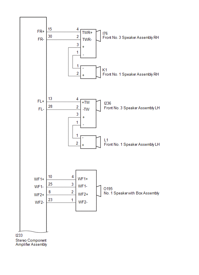
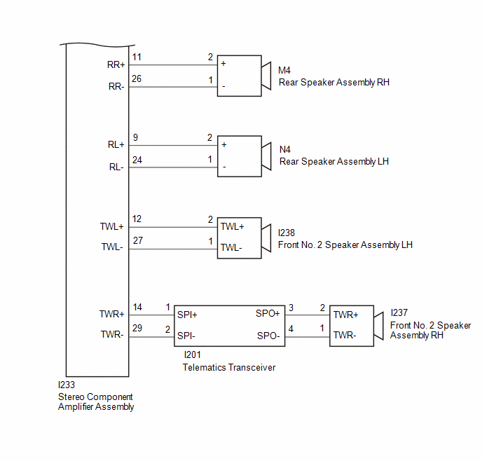
WIRING DIAGRAM
for 6 Speakers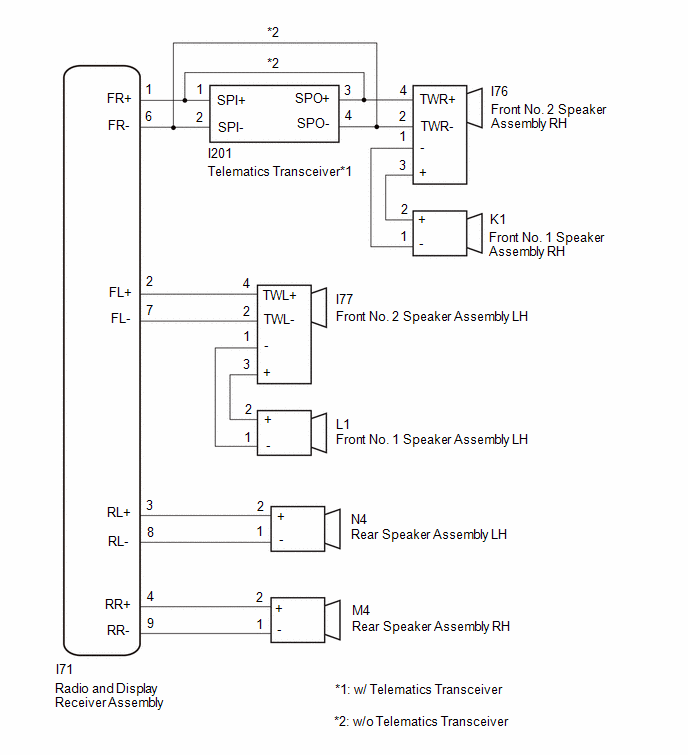 for 9 Speakers
CAUTION / NOTICE / HINT
NOTICE:
- When replacing the telematics transceiver, make sure to replace it with a new one.
- Depending on the parts that are replaced during vehicle inspection or
maintenance, performing initialization, registration or calibration may
be needed.
Click here
.gif)
PROCEDURE
|
1. |
CHECK MODEL |
|
Result |
Proceed to |
|---|---|
|
for 6 Speakers |
A |
|
for 9 Speakers |
B |
| B | .gif)
|
GO TO STEP 15 |
|
.gif)
|
2. |
CHECK MODEL |
|
Result |
Proceed to |
|---|---|
|
w/o Telematics Transceiver |
A |
|
w/ Telematics Transceiver |
B |
| B |
|
GO TO STEP 8 |
|
|
3. |
CHECK HARNESS AND CONNECTOR (RADIO AND DISPLAY RECEIVER ASSEMBLY - EACH SPEAKER) |
(a) Disconnect the I71 radio and display receiver assembly connector.
(b) Disconnect the I77 front No. 2 speaker assembly LH connector.
(c) Disconnect the I76 front No. 2 speaker assembly RH connector.
(d) Disconnect the M4 rear speaker assembly RH connector.
(e) Disconnect the N4 rear speaker assembly LH connector.
(f) Measure the resistance according to the value(s) in the table below.
Standard Resistance:
|
Tester Connection |
Condition |
Specified Condition |
|---|---|---|
|
I71-1 (FR+) - Body ground |
Always |
10 kΩ or higher |
|
I71-2 (FL+) - Body ground |
Always |
10 kΩ or higher |
|
I71-4 (RR+) - Body ground |
Always |
10 kΩ or higher |
|
I71-3 (RL+) - Body ground |
Always |
10 kΩ or higher |
|
I71-6 (FR-) - Body ground |
Always |
10 kΩ or higher |
|
I71-7 (FL-) - Body ground |
Always |
10 kΩ or higher |
|
I71-9 (RR-) - Body ground |
Always |
10 kΩ or higher |
|
I71-8 (RL-) - Body ground |
Always |
10 kΩ or higher |
| NG |
|
REPAIR OR REPLACE HARNESS AND CONNECTOR |
|
|
4. |
CHECK HARNESS AND CONNECTOR (FRONT NO. 2 SPEAKER ASSEMBLY - FRONT NO. 1 SPEAKER ASSEMBLY) |
(a) Disconnect the K1 front No. 1 speaker assembly RH connector.
(b) Disconnect the L1 front No. 1 speaker assembly LH connector.
(c) Disconnect the I77 front No. 2 speaker assembly RH connector.
(d) Disconnect the I76 front No. 2 speaker assembly LH connector.
(e) Measure the resistance according to the value(s) in the table below.
Standard Resistance:
|
Tester Connection |
Condition |
Specified Condition |
|---|---|---|
|
K1-2 (+) - Body ground |
Always |
10 kΩ or higher |
|
L1-2 (+) - Body ground |
Always |
10 kΩ or higher |
|
K1-1 (-) - Body ground |
Always |
10 kΩ or higher |
|
L1-1 (-) - Body ground |
Always |
10 kΩ or higher |
| NG |
|
REPAIR OR REPLACE HARNESS AND CONNECTOR |
|
|
5. |
INSPECT FRONT NO. 1 SPEAKER ASSEMBLY |
Click here
| NG |
|
REPLACE FRONT NO. 1 SPEAKER ASSEMBLY |
|
|
6. |
INSPECT FRONT NO. 2 SPEAKER ASSEMBLY |
Click here
| NG |
|
REPLACE FRONT NO. 2 SPEAKER ASSEMBLY |
|
|
7. |
INSPECT REAR SPEAKER ASSEMBLY |
Click here
| OK |
|
REPLACE RADIO AND DISPLAY RECEIVER ASSEMBLY |
| NG |
|
REPLACE REAR SPEAKER ASSEMBLY |
|
8. |
CHECK HARNESS AND CONNECTOR (RADIO AND DISPLAY RECEIVER ASSEMBLY - EACH SPEAKER, TELEMATICS TRANSCEIVER) |
(a) Disconnect the I71 radio and display receiver assembly connector.
(b) Disconnect the I77 front No. 2 speaker assembly LH connector.
(c) Disconnect the M4 rear speaker assembly RH connector.
(d) Disconnect the N4 rear speaker assembly LH connector.
(e) Disconnect the I201 telematics transceiver connector.
(f) Measure the resistance according to the value(s) in the table below.
Standard Resistance:
|
Tester Connection |
Condition |
Specified Condition |
|---|---|---|
|
I71-1 (FR+) - Body ground |
Always |
10 kΩ or higher |
|
I71-2 (FL+) - Body ground |
Always |
10 kΩ or higher |
|
I71-4 (RR+) - Body ground |
Always |
10 kΩ or higher |
|
I71-3 (RL+) - Body ground |
Always |
10 kΩ or higher |
|
I71-6 (FR-) - Body ground |
Always |
10 kΩ or higher |
|
I71-7 (FL-) - Body ground |
Always |
10 kΩ or higher |
|
I71-9 (RR-) - Body ground |
Always |
10 kΩ or higher |
|
I71-8 (RL-) - Body ground |
Always |
10 kΩ or higher |
| NG |
|
REPAIR OR REPLACE HARNESS AND CONNECTOR |
|
|
9. |
CHECK HARNESS AND CONNECTOR (TELEMATICS TRANSCEIVER - FRONT NO. 2 SPEAKER ASSEMBLY) |
(a) Disconnect the I76 front No. 2 speaker assembly RH connector.
(b) Disconnect the I201 telematics transceiver connector.
(c) Measure the resistance according to the value(s) in the table below.
Standard Resistance:
|
Tester Connection |
Condition |
Specified Condition |
|---|---|---|
|
I201-3 (SPO+) - Body ground |
Always |
10 kΩ or higher |
|
I201-4 (SPO-) - Body ground |
Always |
10 kΩ or higher |
| NG |
|
REPAIR OR REPLACE HARNESS AND CONNECTOR |
|
|
10. |
CHECK HARNESS AND CONNECTOR (FRONT NO. 2 SPEAKER ASSEMBLY - FRONT NO. 1 SPEAKER ASSEMBLY) |
(a) Disconnect the K1 front No. 1 speaker assembly RH connector.
(b) Disconnect the L1 front No. 1 speaker assembly LH connector.
(c) Disconnect the I76 front No. 2 speaker assembly RH connector.
(d) Disconnect the I77 front No. 2 speaker assembly LH connector.
(e) Measure the resistance according to the value(s) in the table below.
Standard Resistance:
|
Tester Connection |
Condition |
Specified Condition |
|---|---|---|
|
K1-2 (+) - Body ground |
Always |
10 kΩ or higher |
|
L1-2 (+) - Body ground |
Always |
10 kΩ or higher |
|
K1-1 (-) - Body ground |
Always |
10 kΩ or higher |
|
L1-1 (-) - Body ground |
Always |
10 kΩ or higher |
| NG |
|
REPAIR OR REPLACE HARNESS AND CONNECTOR |
|
|
11. |
INSPECT FRONT NO. 1 SPEAKER ASSEMBLY |
Click here
| NG |
|
REPLACE FRONT NO. 1 SPEAKER ASSEMBLY |
|
|
12. |
INSPECT FRONT NO. 2 SPEAKER ASSEMBLY |
Click here
| NG |
|
REPLACE FRONT NO. 2 SPEAKER ASSEMBLY |
|
|
13. |
INSPECT REAR SPEAKER ASSEMBLY |
Click here
| NG |
|
REPLACE REAR SPEAKER ASSEMBLY |
|
|
14. |
INSPECT TELEMATICS TRANSCEIVER |
(a) Remove the telematics transceiver.
Click here
|
(b) Measure the resistance according to the value(s) in the table below. Standard Resistance:
|
|
| OK |
|
REPLACE RADIO AND DISPLAY RECEIVER ASSEMBLY |
| NG |
|
REPLACE TELEMATICS TRANSCEIVER |
|
15. |
CHECK HARNESS AND CONNECTOR (STEREO COMPONENT AMPLIFIER ASSEMBLY - EACH SPEAKER, TELEMATICS TRANSCEIVER) |
(a) Disconnect the I233 stereo component amplifier assembly connector.
(b) Disconnect the I238 front No. 2 speaker assembly LH connector.
(c) Disconnect the I76 front No. 3 speaker assembly RH connector.
(d) Disconnect the I236 front No. 3 speaker assembly LH connector.
(e) Disconnect the M4 rear speaker assembly RH connector.
(f) Disconnect the N4 rear speaker assembly LH connector.
(g) Disconnect the O195 No. 1 speaker assembly with box connector.
(h) Disconnect the I201 telematics transceiver connector.
(i) Measure the resistance according to the value(s) in the table below.
Standard Resistance:
|
Tester Connection |
Condition |
Specified Condition |
|---|---|---|
|
I233-15 (FR+) - Body ground |
Always |
10 kΩ or higher |
|
I233-13 (FL+) - Body ground |
Always |
10 kΩ or higher |
|
I233-11 (RR+) - Body ground |
Always |
10 kΩ or higher |
|
I233-9 (RL+) - Body ground |
Always |
10 kΩ or higher |
|
I233-14 (TWR+) - Body ground |
Always |
10 kΩ or higher |
|
I233-12 (TWL+) - Body ground |
Always |
10 kΩ or higher |
|
I233-10 (WF1+) - Body ground |
Always |
10 kΩ or higher |
|
I233-8 (WF2+) - Body ground |
Always |
10 kΩ or higher |
|
I233-30 (FR-) - Body ground |
Always |
10 kΩ or higher |
|
I233-28 (FL-) - Body ground |
Always |
10 kΩ or higher |
|
I233-26 (RR-) - Body ground |
Always |
10 kΩ or higher |
|
I233-24 (RL-) - Body ground |
Always |
10 kΩ or higher |
|
I233-29 (TWR-) - Body ground |
Always |
10 kΩ or higher |
|
I233-27 (TWL-) - Body ground |
Always |
10 kΩ or higher |
|
I233-25 (WF1-) - Body ground |
Always |
10 kΩ or higher |
|
I233-23 (WF2-) - Body ground |
Always |
10 kΩ or higher |
| NG |
|
REPAIR OR REPLACE HARNESS AND CONNECTOR |
|
|
16. |
CHECK HARNESS AND CONNECTOR (TELEMATICS TRANSCEIVER - FRONT NO. 2 SPEAKER ASSEMBLY) |
(a) Disconnect the I237 front No. 2 speaker assembly RH connector.
(b) Disconnect the I201 telematics transceiver connector.
(c) Measure the resistance according to the value(s) in the table below.
Standard Resistance:
|
Tester Connection |
Condition |
Specified Condition |
|---|---|---|
|
I201-3 (SPO+) - Body ground |
Always |
10 kΩ or higher |
|
I201-4 (SPO-) - Body ground |
Always |
10 kΩ or higher |
| NG |
|
REPAIR OR REPLACE HARNESS AND CONNECTOR |
|
|
17. |
CHECK HARNESS AND CONNECTOR (FRONT NO. 3 SPEAKER ASSEMBLY - FRONT NO. 1 SPEAKER ASSEMBLY) |
(a) Disconnect the K1 front No. 1 speaker assembly RH connector.
(b) Disconnect the L1 front No. 1 speaker assembly LH connector.
(c) Disconnect the I76 front No. 3 speaker assembly RH connector.
(d) Disconnect the I236 front No. 3 speaker assembly LH connector.
(e) Measure the resistance according to the value(s) in the table below.
Standard Resistance:
|
Tester Connection |
Condition |
Specified Condition |
|---|---|---|
|
K1-2 (+) - Body ground |
Always |
10 kΩ or higher |
|
L1-2 (+) - Body ground |
Always |
10 kΩ or higher |
|
K1-1 (-) - Body ground |
Always |
10 kΩ or higher |
|
L1-1 (-) - Body ground |
Always |
10 kΩ or higher |
| NG |
|
REPAIR OR REPLACE HARNESS AND CONNECTOR |
|
|
18. |
INSPECT FRONT NO. 1 SPEAKER ASSEMBLY |
Click here
| NG |
|
REPLACE FRONT NO. 1 SPEAKER ASSEMBLY |
|
|
19. |
INSPECT FRONT NO. 2 SPEAKER ASSEMBLY |
Click here
| NG |
|
REPLACE FRONT NO. 2 SPEAKER ASSEMBLY |
|
|
20. |
INSPECT FRONT NO. 3 SPEAKER ASSEMBLY |
Click here
| NG |
|
REPLACE FRONT NO. 3 SPEAKER ASSEMBLY |
|
|
21. |
INSPECT REAR SPEAKER ASSEMBLY |
Click here
| NG |
|
REPLACE REAR SPEAKER ASSEMBLY |
|
|
22. |
INSPECT NO. 1 SPEAKER WITH BOX ASSEMBLY |
Click here
| NG |
|
INSPECT NO. 1 SPEAKER WITH BOX ASSEMBLY |
|
|
23. |
INSPECT TELEMATICS TRANSCEIVER |
(a) Remove the telematics transceiver.
Click here
|
(b) Measure the resistance according to the value(s) in the table below. Standard Resistance:
|
|
| OK |
|
REPLACE STEREO COMPONENT AMPLIFIER ASSEMBLY |
| NG |
|
REPLACE TELEMATICS TRANSCEIVER |


